
Magnetic head with heater of thermal flying height control

a technology of magnetic head and heater, which is applied in the direction of maintaining the head carrier alignment, recording information storage, instruments, etc., can solve the problems of reducing the size of the slider and the magnetic read/write device, and affecting the accuracy of the control

Inactive Publication Date: 2006-02-16
WESTERN DIGITAL TECH INC
View PDF1 Cites 22 Cited by
  • Summary
  • Abstract
  • Description
  • Claims
  • Application Information

AI Technical Summary

Benefits of technology

[0007] It is a feature of the present invention to provide a magnetic head slider capable of preventing electrical leakage between a heat generating resistor and a metal film in the vicinity thereof.
[0008] It is another feature of the invention to provide a magnetic head slider capable of preventing electrical leakage between a heat generating resistor and a metal film in the vicinity thereof and improving the response speed for the flying height control without increasing the temperature of a magnetoresistive device.
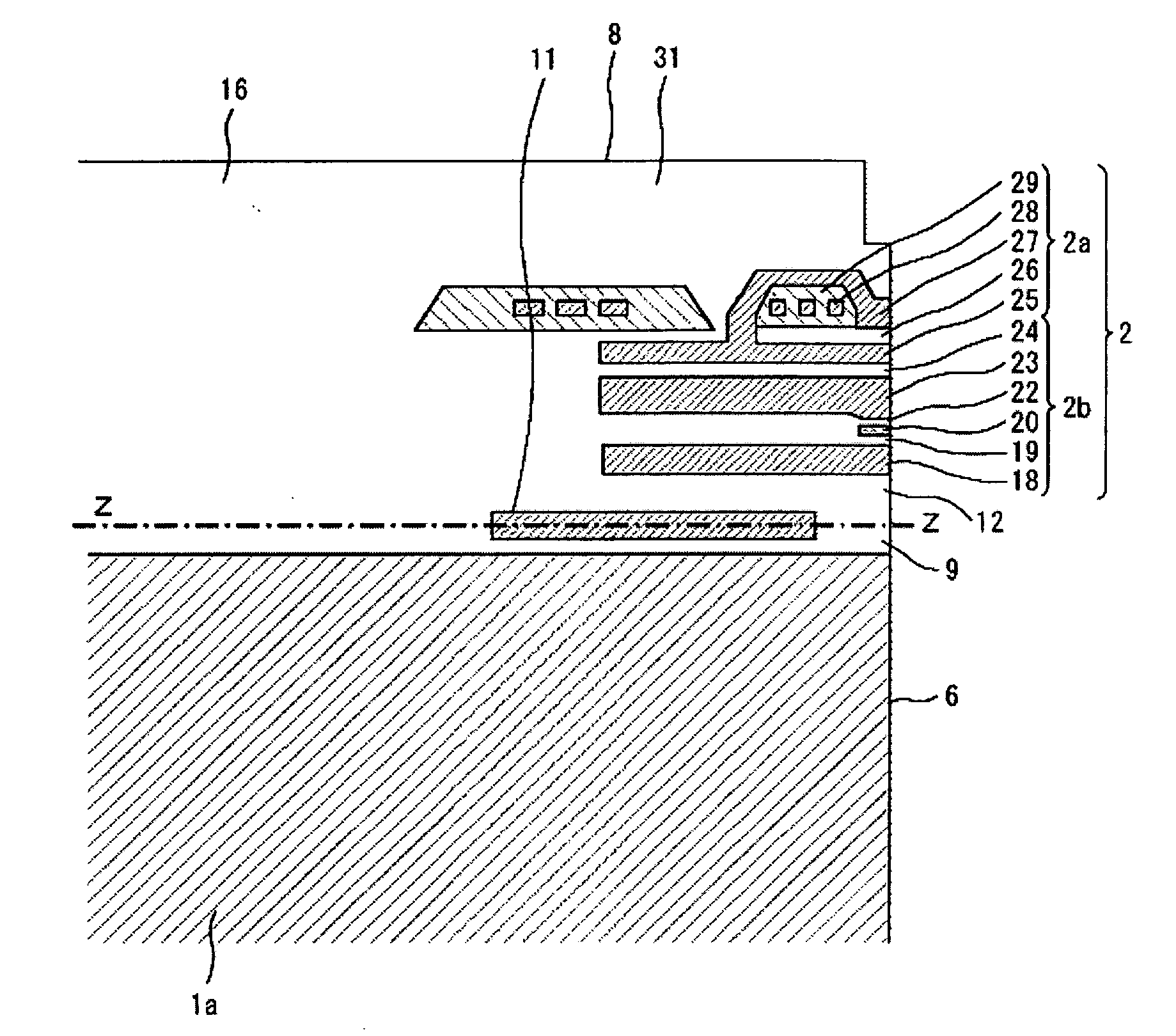
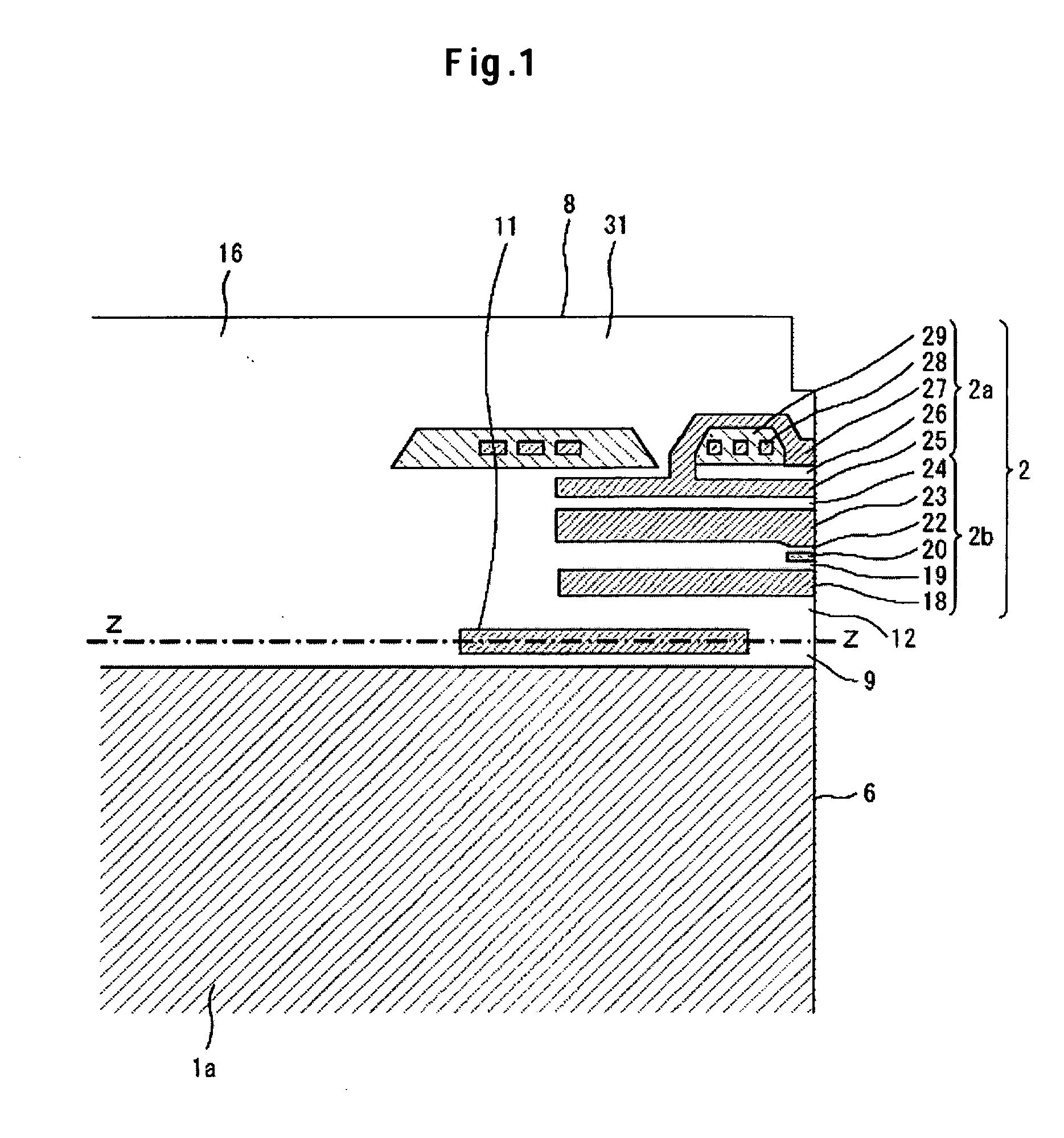
[0016] According to the invention, electrical leakage between the heat generating resistor for flying height control and a metal film in the vicinity thereof can be prevented in a magnetic head slider having a function of flying height controlling. FIG. 1 is an enlarged cross-sectional partial view (cross-sectional view taken along line X-X in FIG. 4) of a magnetic head slider according to an embodiment of the present invention.

Problems solved by technology

Accordingly, if an insulating film has a thickness not large enough to ensure insulation between the heat generating resistor and a metal film such as a magnetic pole piece situated in the vicinity thereof is not large enough, there occurs a problem of causing electrical leakage between the heat generating resistor and the magnetic film such as the magnetic pole piece.
This problem becomes conspicuous, particularly, as the size of the slider and the magnetic read / write device is decreased for higher recording density.

Method used


Image

  • Magnetic head with heater of thermal flying height control
  • Magnetic head with heater of thermal flying height control
  • Magnetic head with heater of thermal flying height control

Examples


Embodiment Construction

[0025] A description will be made of a magnetic head slider and a magnetic disk drive using the slider in accordance with embodiments of the present invention with reference to the drawings.

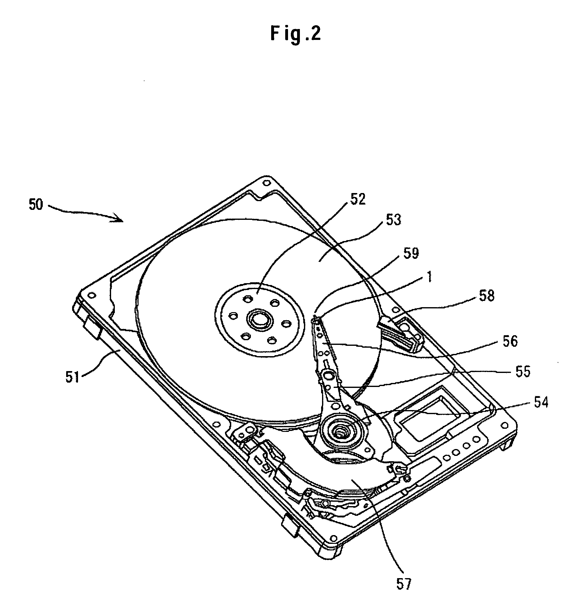
[0026]FIG. 2 shows a constitution of a magnetic disk drive 50. A magnetic disk 53 is mounted to a rotary shaft 52 of a spindle motor fixed to a base 51 and is driven in rotation. An actuator arm 55 is journaled on a pivot 54 and a suspension 56 is attached to one end and a coil (not illustrated) constituting a driving device (voice coil motor) 57 is attached to the other end of the actuator arm 55. A magnetic head slider 1 is attached to the top end of the suspension 56. A ramp mechanism 58 is provided on the base 51 and situated on the outer periphery of the magnetic disk 53. The ramp mechanism 58 has a slope over which a lift tab 59 rides over upon unloading of the magnetic head slider 1.

[0027] When a current is supplied to the coil of the voice coil motor 57, rotary torque is generated in th...


PUM

PropertyMeasurementUnit
flying heightaaaaaaaaaa
widthaaaaaaaaaa
lengthaaaaaaaaaa

Abstract

In one embodiment, a magnetic write / read device comprising a magnetic read element and a magnetic write element is formed in a thin film magnetic head portion of a magnetic head slider. A heat generating resistor is formed between a substrate portion and the magnetic reproducing device for heating thereby thermally expanding and protruding a portion of the magnetic head slider to control the flying height. The heat generating resistor is positioned between the substrate portion and the magnetic reproducing device being apart from the magnetic reproducing device for making the response speed for the flying height control of the magnetic head slider as high as possible and decreasing the effect caused by the heat generation of the heat generating resistor on the magnetic reproducing device as little as possible. The thickness of the insulating film is made greater than 10 times or less that of the heat generating resistor for ensuring insulation between the heat generating resistor and the metal film of a lower shield film.

Description

CROSS-REFERENCES TO RELATED APPLICATIONS [0001] This application claims priority from Japanese Patent Application No. JP2004-233251, filed Aug. 10, 2004, the entire disclosure of which is incorporated herein by reference. BACKGROUND OF THE INVENTION [0002] The present invention relates to a structure of a magnetic head slider for attaining high-density recording in a magnetic disk drive. In particular, the invention relates to a flying height controlling slider having a function of controlling the distance between a magnetic disk and a magnetic head. [0003] A magnetic disk drive comprises a rotating magnetic disk and a slider having a magnetic read / write device constituting a magnetic head mounted thereon and supported by a suspension, in which the slider runs relatively on the magnetic disk to read and write magnetic information to the magnetic disk. The slider flies by the air edging film effect as an air lubrication bearing, so that the magnetic disk and the slider are not in dir...

Claims


Application Information

Patent Timeline
Patent Type & Authority Applications(United States)
IPC IPC(8): G11B5/41
CPCG11B5/3106G11B5/314G11B5/6064G11B5/6005G11B5/40G11B5/607
Inventor KATO, ATSUSHISHIRAMATSU, TOSHIYASOGA, MASAHIKO
Owner WESTERN DIGITAL TECH INC
Learn More