Thermal control system for rack mounting

Inactive Publication Date: 2006-02-16
THERMOTEK
View PDF35 Cites 67 Cited by
  • Summary
  • Abstract
  • Description
  • Claims
  • Application Information

AI Technical Summary

Benefits of technology

[0017] In yet another embodiment, the above-described invention includes the ability to customize the design of the 3U system and allow on the order of three heat transfer assemblies to effect cooling and

Problems solved by technology

By mounting multiple components in a rack heat is increased, thereby causing deterioration and possible failure of many of the components.
In addition, many components, such as laser systems, perform poorly when subject to vibration and noise that many compressor-based chillers exhibit.
It should be noted, however, that such height is critical to space considerations of the overall rack.
These com

Method used


Image

  • Thermal control system for rack mounting
  • Thermal control system for rack mounting
  • Thermal control system for rack mounting

Examples


Embodiment Construction

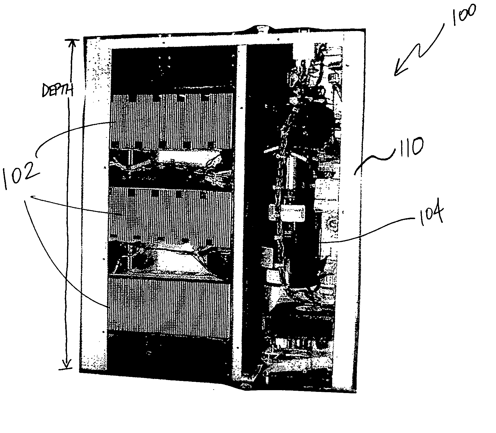
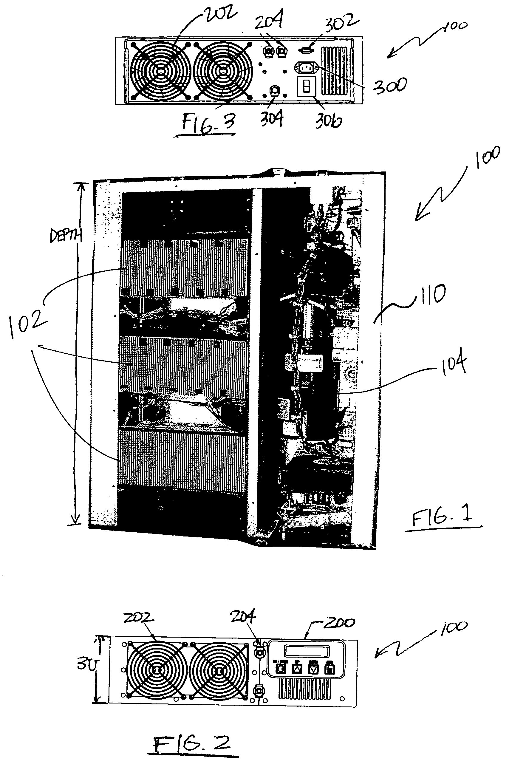
[0025] Referring now to FIG. 1, a top view of a temperature control system 100 in accordance with an embodiment of the present invention is illustrated. The temperature control system 100 utilizes a heat transfer fluid that is circulated in a closed loop to cool or heat components within a conventional rack. The heat transfer fluid may be, for example, a water / glycol mixture, although other heat transfer fluids may be utilized. In one embodiment, three HTA modules 102 are utilized to effect cooling and / or heating in the temperature control system 100, however embodiments of the present invention may include more or fewer HTA modules as desired. The temperature control system 100 may also include up to six internal fan assemblies (not shown) and an addition three internal fans with an external fan train. The fans may be oriented in a push / pull fan arrangement or other arrangement as desired. In alternate embodiments, fans on the heat transfer side are not included. Instead, the tempe...


PUM


Abstract

A thermal control system of a 3U height includes various modules for providing temperature control in a rack environment. The modules may be, for example, a power module, user interface module, various different pump assemblies, various different models of fan assemblies, HTAs, and/or a serial communication interfaces. This Abstract is provided to comply with rules requiring an Abstract that allows a searcher or other reader to quickly ascertain subject matter of the technical disclosure. This Abstract is submitted with the understanding that it will not be used to interpret or limit the scope or meaning of the claims. 37 CFR 1.72(b).

Description

RELATED APPLICATIONS[0001] The present application claims priority to U.S. Provisional Patent Application No. 60 / 601,013 filed Aug. 12, 2004, and incorporates by reference for all purposes the entire disclosures of U.S. patent application Ser. No. 09 / 328,183 filed Jun. 8, 1999 and U.S. Pat. No. 6,462,949 entitled “Electronic Enclosure Cooling System.”BACKGROUND OF THE INVENTION [0002] 1. Technical Field [0003] The present invention relates to thermal control systems, and more particularly, but not by way of limitation, to low profile, rack mounted thermal control systems for cooling or heating equipment disposed in or in the vicinity of an equipment rack. [0004] 2. Background of the Related Art [0005] As the evolution of computers continued from mini-computers that filled entire rooms with equipment to PC modules similar to the personal computer known today, rack mounted equipment decreased in popularity. However, with the introduction of new electronic equipment, such as slice serv...

Claims


Application Information

Patent Timeline
IPC IPC(8): H05K7/20
CPCH05K7/20772
Inventor PARISH, OVERTON L.BALACHANDRAN, NIRANQUISENBERRY, TONYLEGGETT, WILLIAM F.
Owner THERMOTEK
Why Eureka
Try Eureka