System and method for dynamic skeletal stabilization

a dynamic and skeletal technology, applied in the field of skeletal stabilization, can solve the problems of limiting the patient's movement, further complications, and no provision for preventing or reducing disc compression, and achieve the effect of substantial range of motion

Inactive Publication Date: 2006-02-16
THEKEN SPINE
View PDF18 Cites 586 Cited by
  • Summary
  • Abstract
  • Description
  • Claims
  • Application Information

AI Technical Summary

Benefits of technology

[0009] There is disclosed a system and method for dynamic stabilization which provides for distraction of the inter-vertebral space while still allowing a patient a substantial range of motion. In one embodiment, an inter-vertebral dynamic brace is used to maintain proper distraction. The dynamic brace is designed to allow the vertebrae to which it is attached to move through its natural ar...

Problems solved by technology

This not only limits the patient's movements but also places additional stress on other portions of the spine (typically, the stress placed on adjacent vertebrae being the worse), often leading to further complications at a later date.
In still another attempt to solve the compression problem, a lever arm approach ha...

Method used


Image

  • System and method for dynamic skeletal stabilization
  • System and method for dynamic skeletal stabilization
  • System and method for dynamic skeletal stabilization

Examples


Embodiment Construction

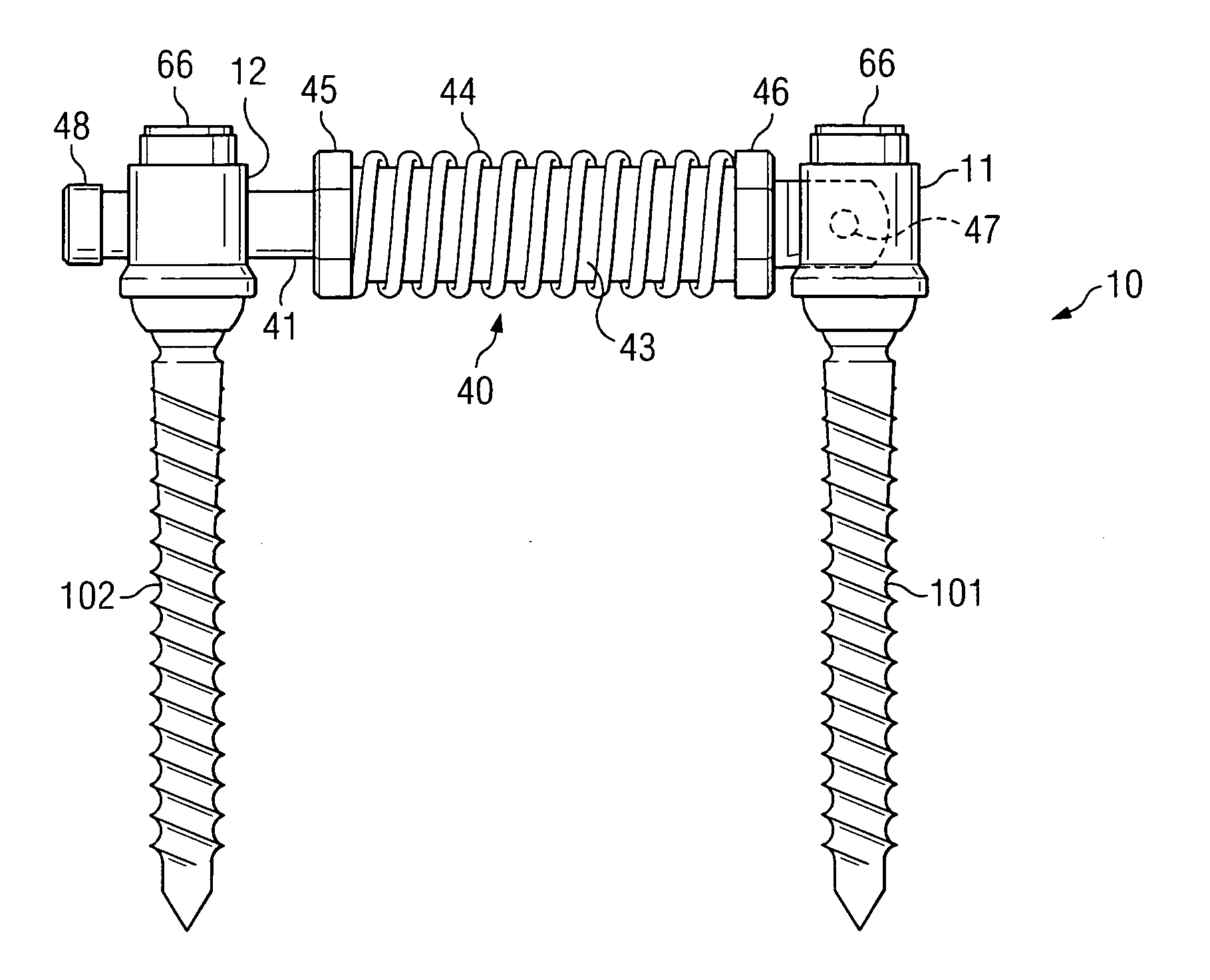
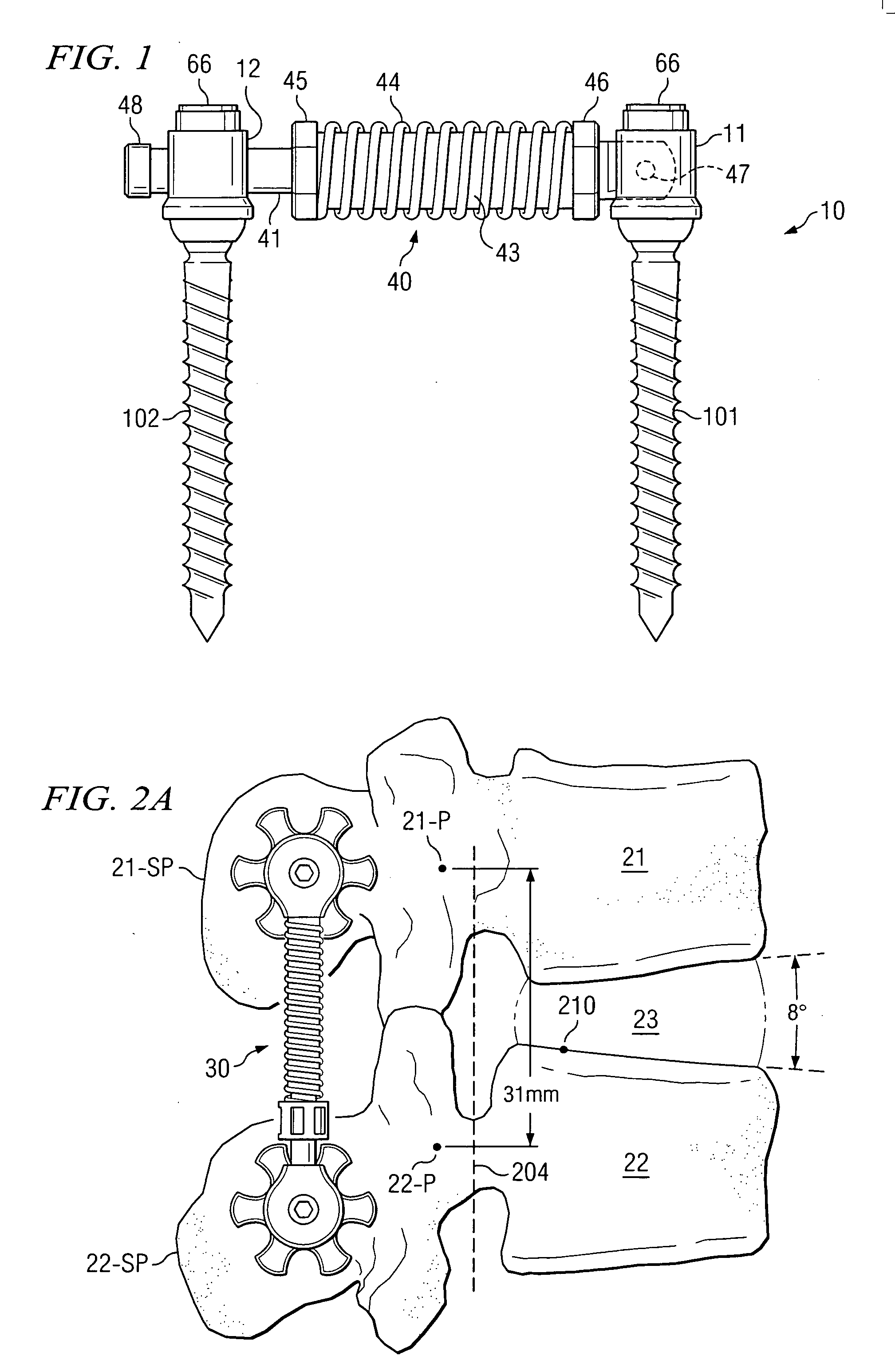
[0022]FIG. 1 shows dynamic brace (or “rod”) 40 positioned with respect to pedicle screws 101 and 102 in system 10. This is but one embodiment of the manner in which a dynamic stabilization device can be employed to partially off-load (or un-weight) the disc between vertebrae (to reduce compression forces) so that as the spine moves through its normal range of motion pressure on the disc is reduced throughout the entire range of motion. In this embodiment, the pedicle screws are positioned in the pedicles of the spine as discussed and shown in the above-identified co-pending U.S. Patent Application entitled “SYSTEM AND METHOD FOR STABILIZING INTERNAL STRUCTURES.”FIGS. 6A through 6F discussed below show in more detail how and where the pedicle screws are implanted for a dynamic brace in accordance with one procedure.

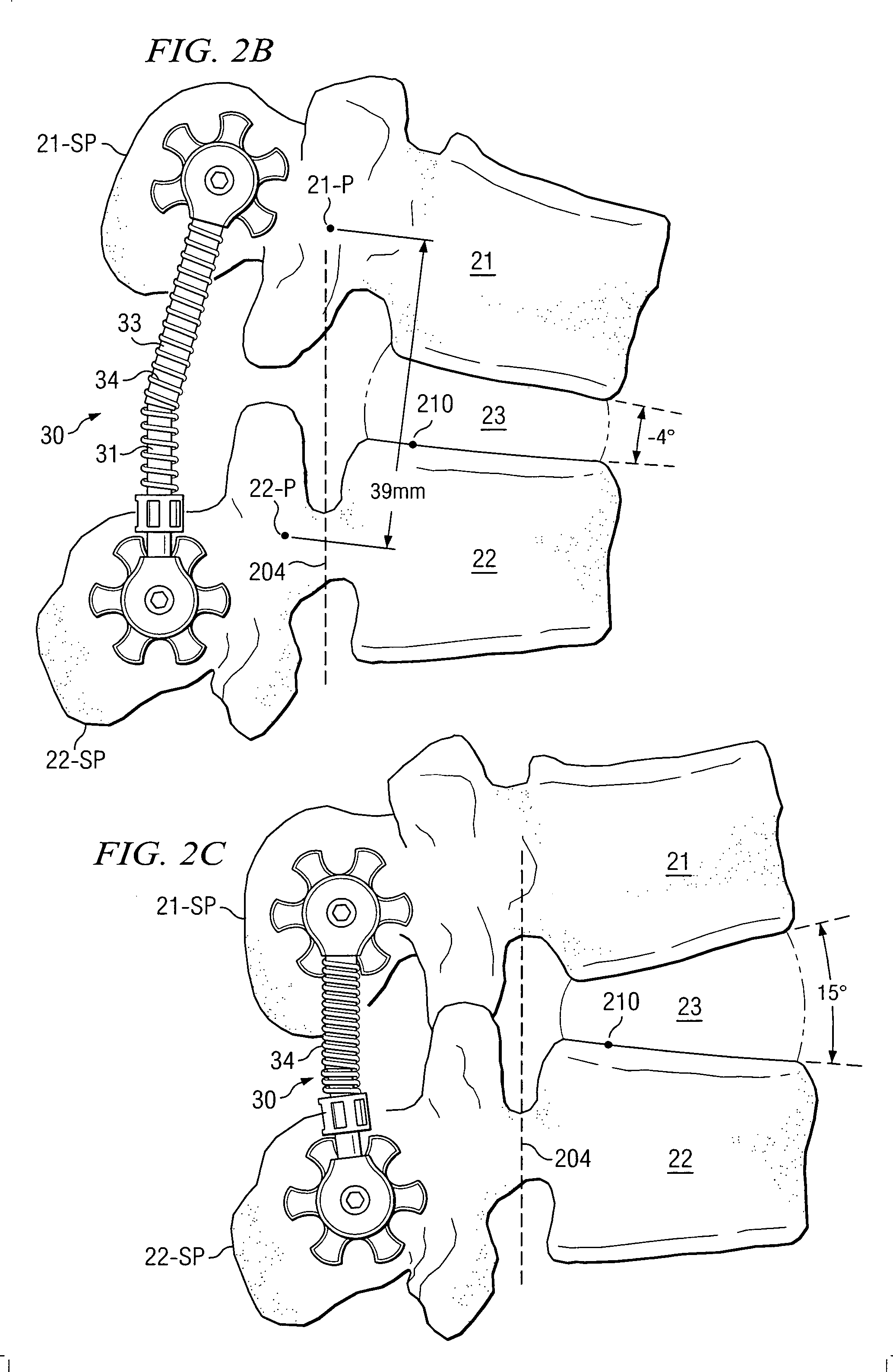
[0023] As will be discussed, one of the purposes of the dynamic brace is so that as adjacent pedicles move with respect to each other they are free to follow their natura...


PUM


Abstract

There is disclosed a system and method for dynamic stabilization which provides for distraction of the inter-vertebral space while still allowing a patient a substantial range of motion. In one embodiment, an inter-vertebral dynamic brace is used to maintain proper distraction. The dynamic brace is designed to allow the vertebrae to which it is attached to move through their natural arc, maintaining the correct instantaneous center of rotation. An adjustable tensioning device is used to maintain the proper distraction and compression forces to restore and maintain proper kinematics, while allowing the dynamic brace to move through an arc centered with respect to the center of rotation of the portion of the spine between the vertebrae. In one embodiment, a method is provided for adjusting the dynamic brace both with respect to the center of rotation of the vertebrae in both the flexion/extension axis and in the superior/inferior axis.

Description

CROSS-REFERENCE TO RELATED APPLICATIONS [0001] The present application is related to co-pending, and commonly assigned U.S. patent application Ser. No. 10 / 690,211, entitled “SYSTEM AND METHOD FOR STABILIZING INTERNAL STRUCTURES,” filed Oct. 21, 2003, the disclosure of which is hereby incorporated herein by reference. TECHNICAL FIELD [0002] This disclosure relates to skeletal stabilization and more particularly to systems and methods for stabilization of human spines and even more particularly to dynamic stabilization techniques. BACKGROUND OF THE INVENTION [0003] The skeletal system, particularly the human spine, is a complex structure designed to achieve a myriad of tasks, many of them of a complex kinematic nature. While performing its function, the spine must move into flexion (bending forward) and extension (bending backward). For example, the vertebrae that make up the lumbar region of the human spine move through roughly an arc of 15° relative to its neighbor vertebrae. Verteb...

Claims


Application Information

Patent Timeline
IPC IPC(8): A61F2/30
CPCA61B17/7023A61B17/7025A61B17/7028A61B17/7085A61B17/7049A61B17/7062A61B17/7044
Inventor COLLERAN, DENNISSCHORER, SCOTTMCAFEE, PAUL
Owner THEKEN SPINE
Why Eureka
Try Eureka