Rigidly guided implant placement

a placement method and implant technology, applied in the field of spinal fixation devices, can solve the problems of affecting the treatment effect of patients, so as to achieve the effect of avoiding the occurrence of undesirable symptoms, prolonging radiation exposure to patients, and avoiding surgery

Active Publication Date: 2006-02-16
DEPUY SYNTHES PROD INC
View PDF60 Cites 129 Cited by
  • Summary
  • Abstract
  • Description
  • Claims
  • Application Information

AI Technical Summary

Problems solved by technology

Misalignment of the pedicle screws during insertion can cause the screw body or its threads to break through the vertebral cortex and be in danger of striking surrounding nerve roots.
A variety of undesirable symptoms can easily arise when the screws make contact with nerves after breaking outside the pedicle cortex, including dropped foot, neurological lesions, sensory deficits, or pain.
However, prolonged radiation exposure to a patient and a surgeon is undesirable.
However, these systems are extremely expensive, require significant training, are cumbersome in operation, are difficult to maintain, and are not cost effective for many hospitals.
Therefore, the position of the tool guide is subject to human error, fatigue and slippage, and requires continued operation of expensive equipment and prolonged exposure to radiation to maintain.

Method used


Image

  • Rigidly guided implant placement
  • Rigidly guided implant placement
  • Rigidly guided implant placement

Examples


Embodiment Construction

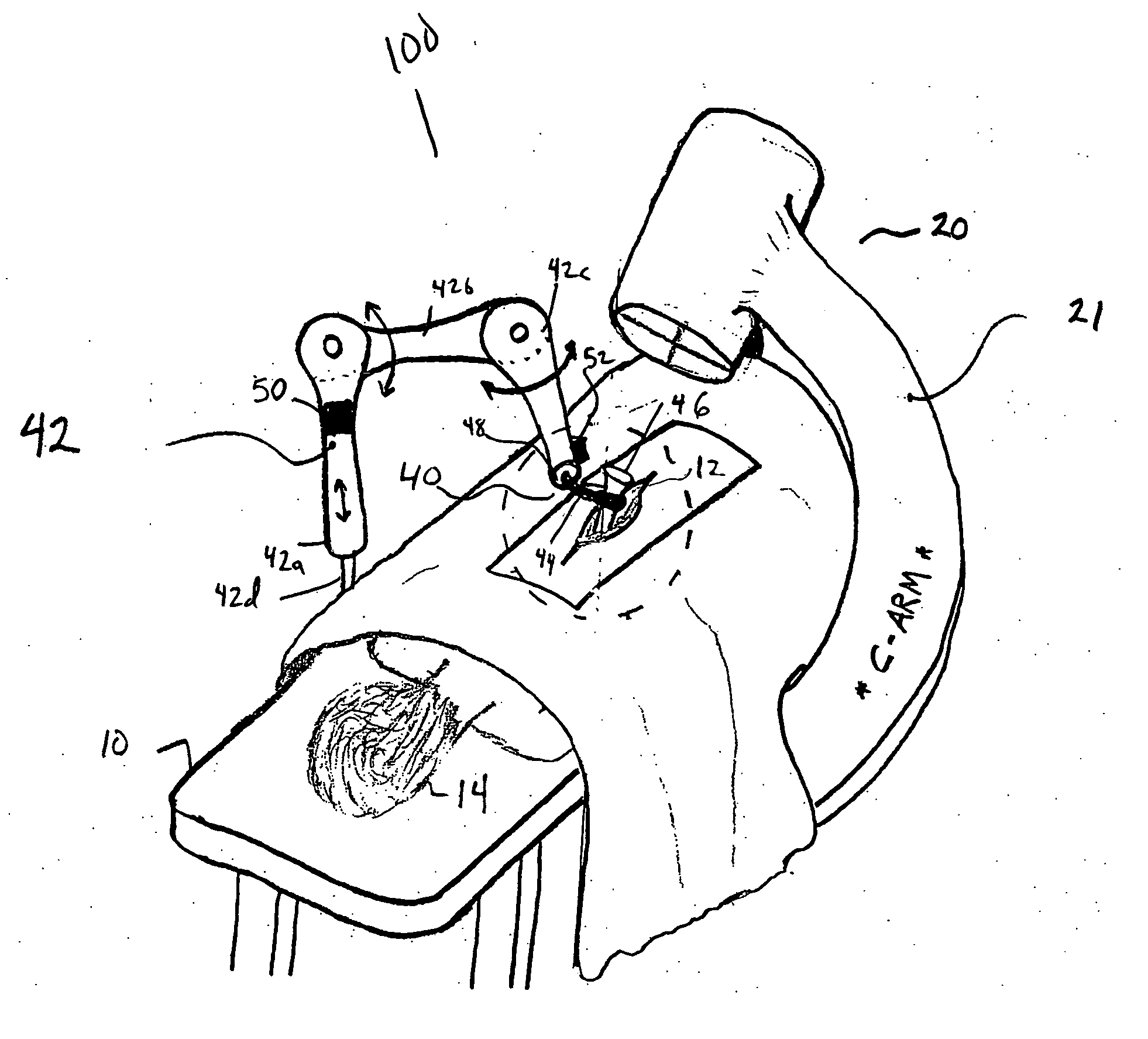
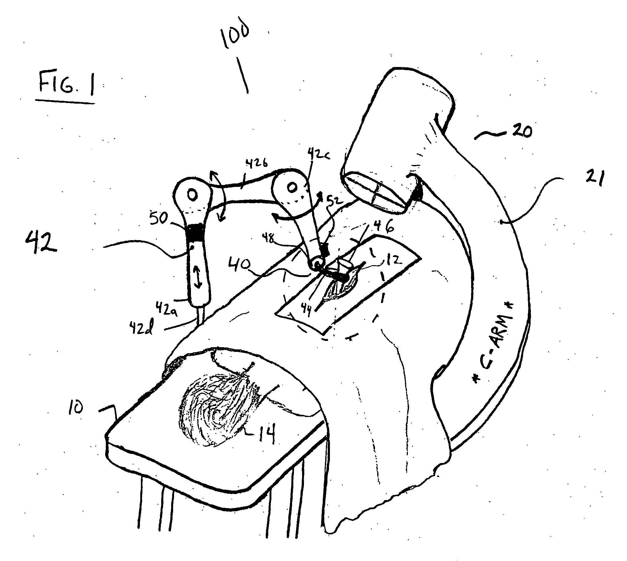
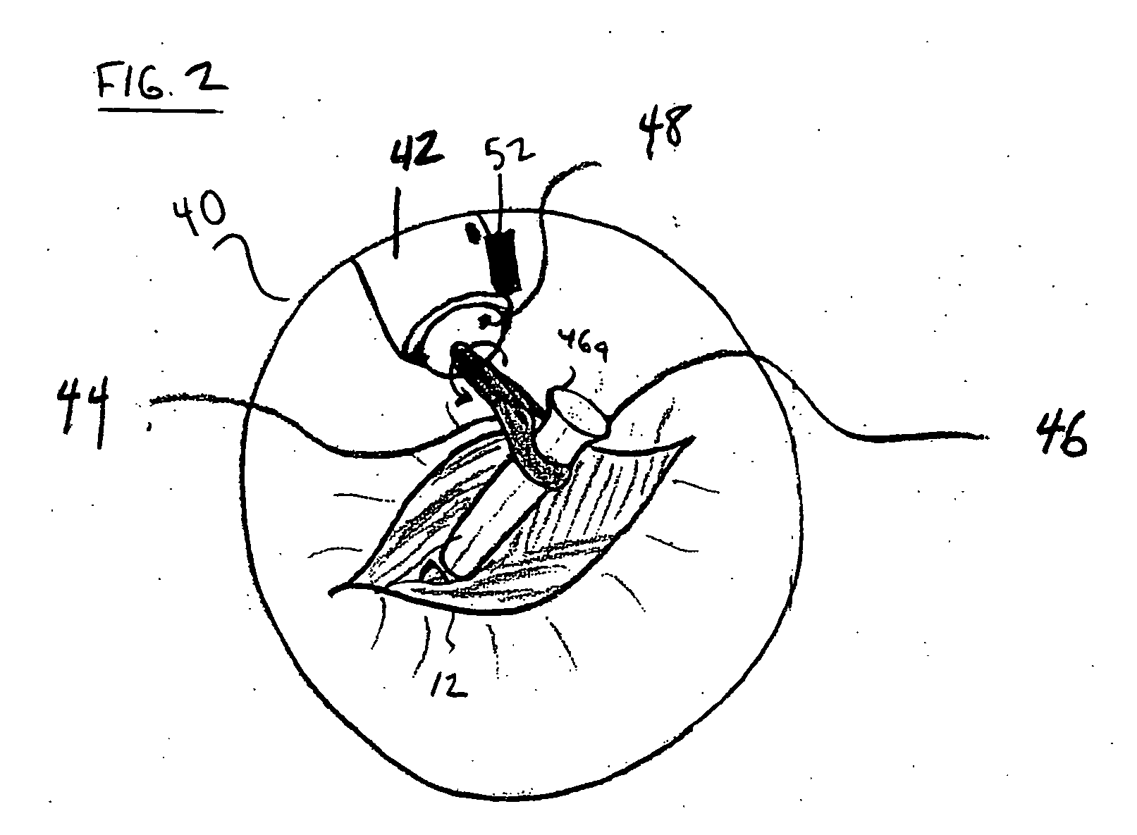
[0028] The present invention provides an improved guidance system and method for guiding an implant, such as a pedicle screw, along a predetermined trajectory. The present invention will be described below relative to an illustrative embodiment. Those skilled in the art will appreciate that the present invention may be implemented in a number of different applications and embodiments and is not specifically limited in its application to the particular embodiments depicted herein.

[0029] The guidance system of an illustrative embodiment of the invention is used to insert a pedicle screw into a vertebra, though one skilled in the art will recognize that the invention can be used to place any suitable implant that requires a known trajectory. Examples of surgical procedures suitable for employing the guidance system of the present invention include, but are not limited to, insertion of interbody fusion devices, bone anchors, fixation devices, including rods, plates and cables, artifici...


PUM


Abstract

A system for guiding an implant to an optimal placement within a patient includes a trajectory guide for guiding instruments along a selected trajectory and a trajectory fixation device for fixing the trajectory guide in a selected position. The trajectory guide defines a path configured to align with the selected trajectory. A movable support mounts the trajectory guide and selectively moves the trajectory guide to align the trajectory guide with the selected trajectory prior to fixing the trajectory guide in the selected position. After fixing the trajectory guide, instruments can be inserted along the trajectory through the path defined by the trajectory guide.

Description

FIELD OF THE INVENTION [0001] The present invention relates to spinal fixation devices used in orthopedic surgery. More particularly, the present invention relates to instrumentation and a method for the optimal placement of surgical implements and implants. BACKGROUND OF THE INVENTION [0002] Spinal fixation systems may be used in orthopedic surgery to align, stabilize and / or fix a desired relationship between adjacent vertebral bodies. Such systems typically include a spinal fixation element, such as a relatively rigid fixation rod or plate, extending along an axis along which the vertebral bodies are to be positioned and coupled to adjacent vertebrae by attaching the element to various anchoring devices, such as hooks, bolts, wires or screws. The spinal fixation element can have a predetermined contour that has been designed according to the properties of the target implantation site and, once installed, the spinal fixation element holds the vertebrae in a desired spatial relation...

Claims


Application Information

Patent Timeline
Patent Type & Authority Applications(United States)
IPC IPC(8): A61B19/00
CPCA61B19/201A61B19/26A61B19/5244A61B2019/5255A61B2019/202A61B2019/507A61B2017/3409A61B90/11A61B34/20A61B90/13A61B90/50A61B2034/107A61B2034/2055B07C2501/0009
Inventor SELOVER, SEANSICVOL, CHRISTOPHER W.NAUGHTON, RONALDSHEEHY, NANCY M.BIRKMEYER, PAUL
Owner DEPUY SYNTHES PROD INC
Why Eureka
Try Eureka