Selector mechanism for a motor vehicle transmission
- Summary
- Abstract
- Description
- Claims
- Application Information
AI Technical Summary
Benefits of technology
Problems solved by technology
Method used
Image
Examples
Embodiment Construction
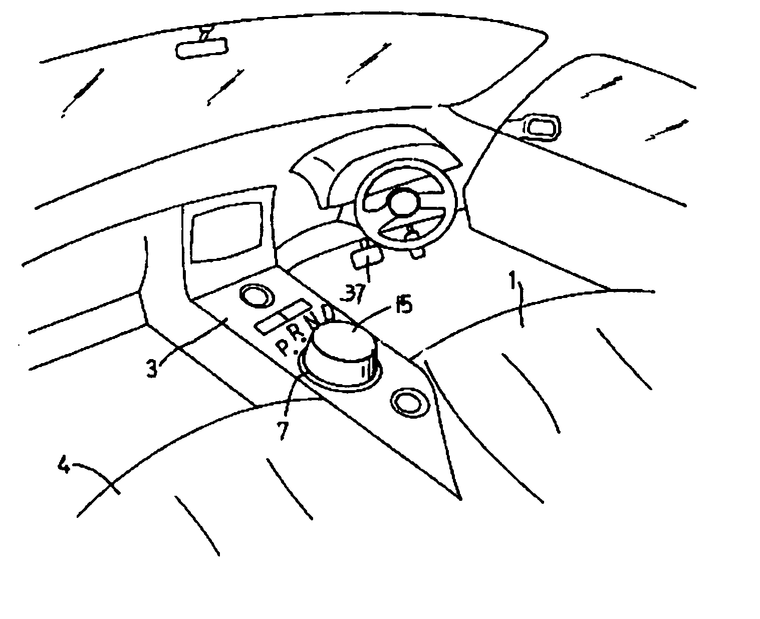
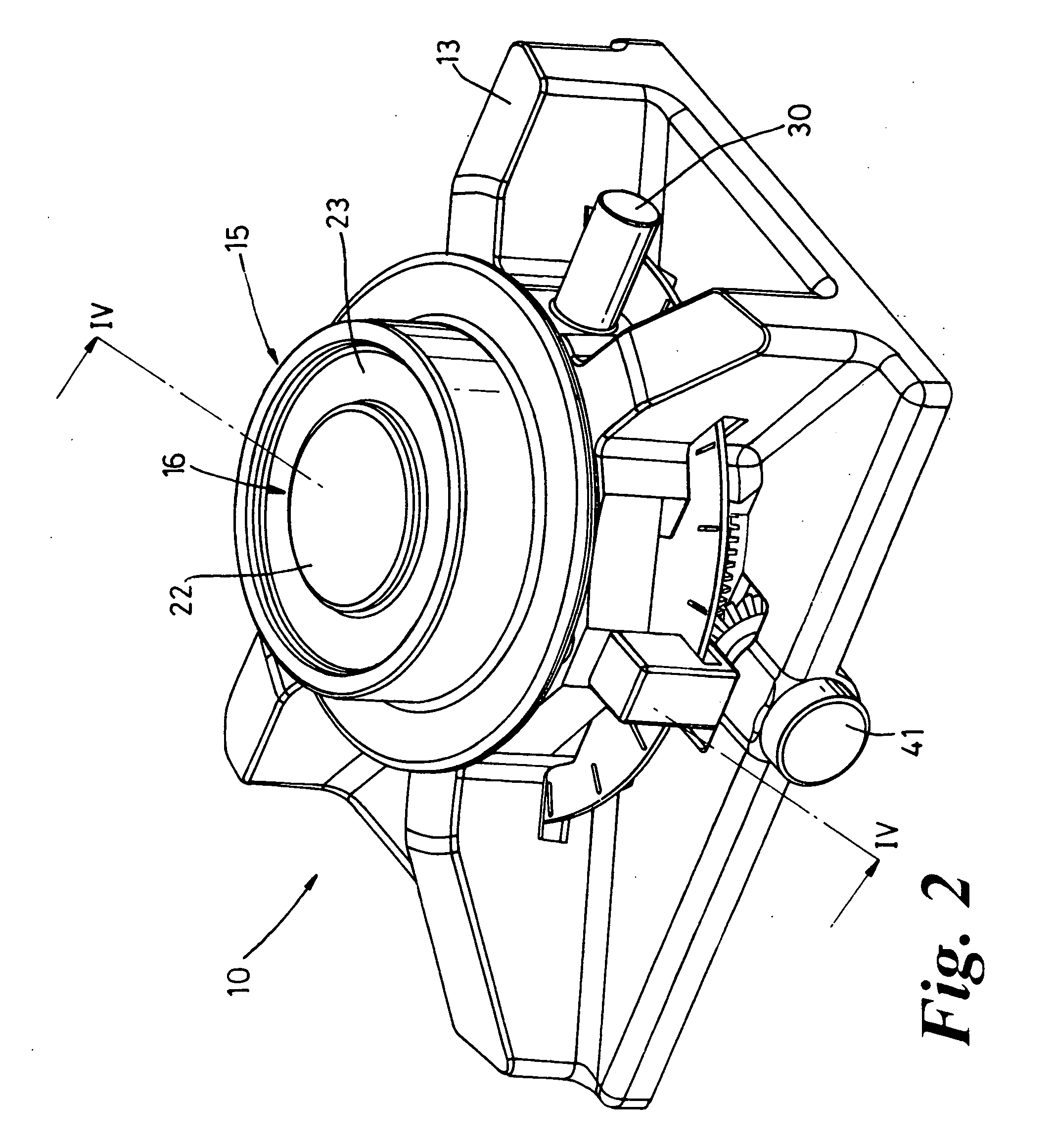
[0039] With reference to the drawings, there is shown a rotatable selector mechanism 10 for actuating an automatic vehicle transmission 11 driven by an engine 12. The rotatable selector mechanism 10 is located in an upper surface of a console mounted between a driver's seat and a passenger seat.
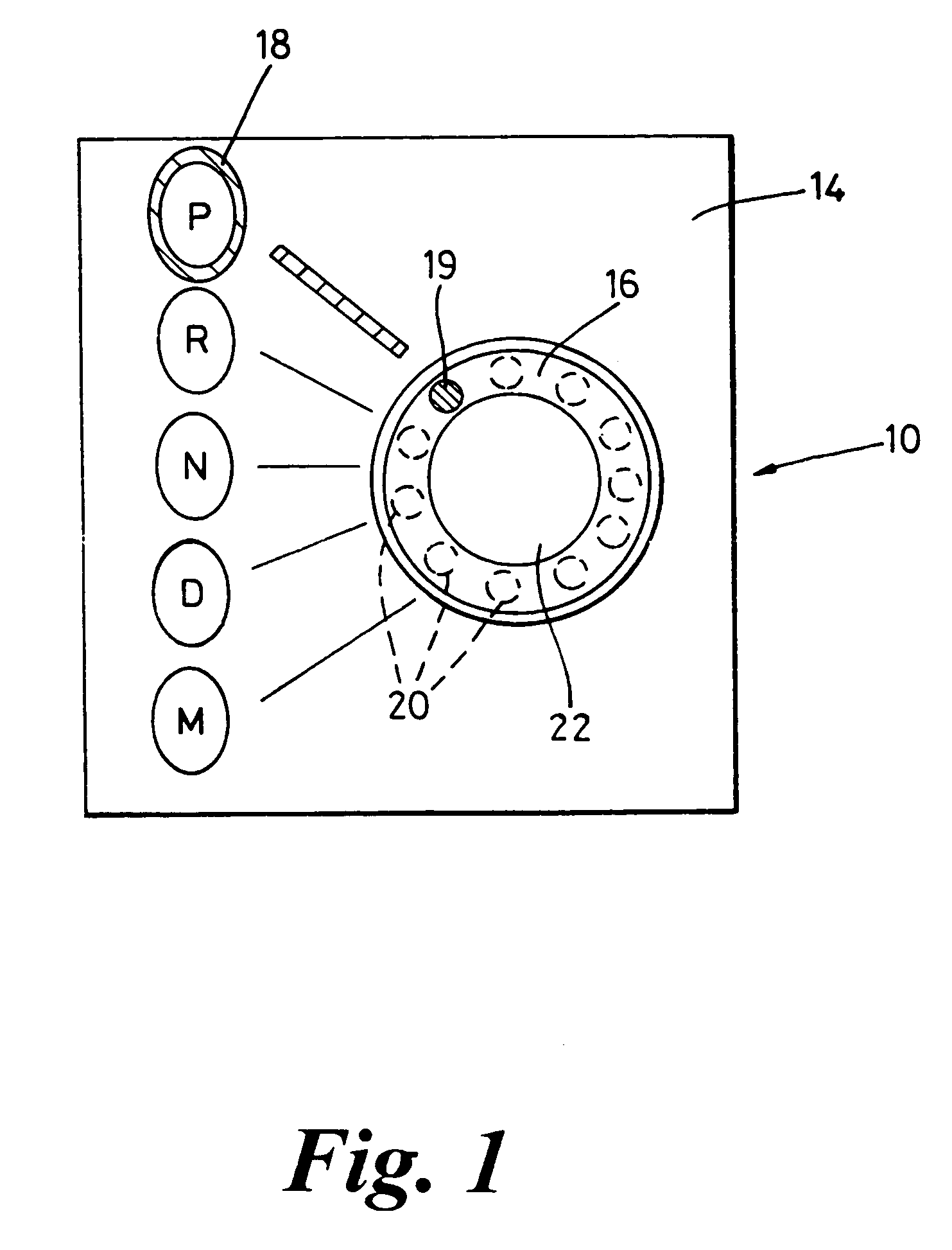
[0040] The selector mechanism 10 includes a housing formed by a base 13 and a part 14 of the console inside which a rotary handle in the form of a selector knob 15 is rotatable around a substantially vertical fixed shaft 17 mounted to the base 13. The selector knob 15 can be grasped by the driver and rotated around the shaft 17 to select the operating mode of the transmission by pointing an illuminated pointer 16 towards one of a number of labels constituted by the letters PRND. These letters correspond to the Park (P), Reverse (R), Neutral (N) and Drive (D) modes respectively in the automatic transmission (FIG. 1) and are arranged in a straight line near the selector knob 15.
[0041] Each la...
PUM
 Abstract
Description
Claims
Application Information
 - R&D
- Intellectual Property
- Life Sciences
- Materials
- Tech Scout
- Unparalleled Data Quality
- Higher Quality Content
- 60% Fewer Hallucinations
Browse by: Latest US Patents, China's latest patents, Technical Efficacy Thesaurus, Application Domain, Technology Topic, Popular Technical Reports.
© 2025 PatSnap. All rights reserved.Legal|Privacy policy|Modern Slavery Act Transparency Statement|Sitemap|About US| Contact US: help@patsnap.com


