
Spinal Rod

Active Publication Date: 2010-03-11
LIFE SPINE
View PDF21 Cites 120 Cited by
  • Summary
  • Abstract
  • Description
  • Claims
  • Application Information

AI Technical Summary

Benefits of technology

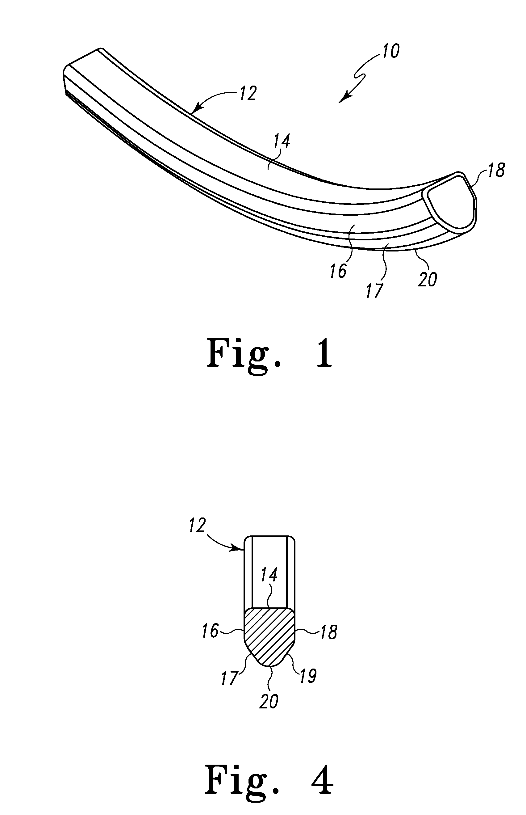
[0013]In one form, the spine rod has an essentially pentagonal cross-section that thus essentially defines angled sides or side surfaces that interact with a configured spinal rod opening of a spine rod holder to positively seat the spine rod into the spinal rod holder. In this manner, the spine rod is prevented from rotational movement within the spinal rod holder.

Problems solved by technology

In the case of degenerative disc disease, spinal trauma and the like, such conditions are often painful and / or physically deforming.
A drawback of current spinal rods relates to reception and seating of the spinal rod into the spinal rod holder / bone anchor assembly.
This low amount of contact area does not allow a good seating of the spinal rod into the rod holder.
The spinal rod may be subject to loading that occurs on the stabilizing assemblies and especially on the anchoring sites during normal activity.
These loads may result in loosening of the assembly from the vertebrae or even breaking of the assembly if there is not proper seating of the spinal rod in the spinal rod holder.

Method used


Image

  • Spinal Rod
  • Spinal Rod
  • Spinal Rod

Examples


Embodiment Construction

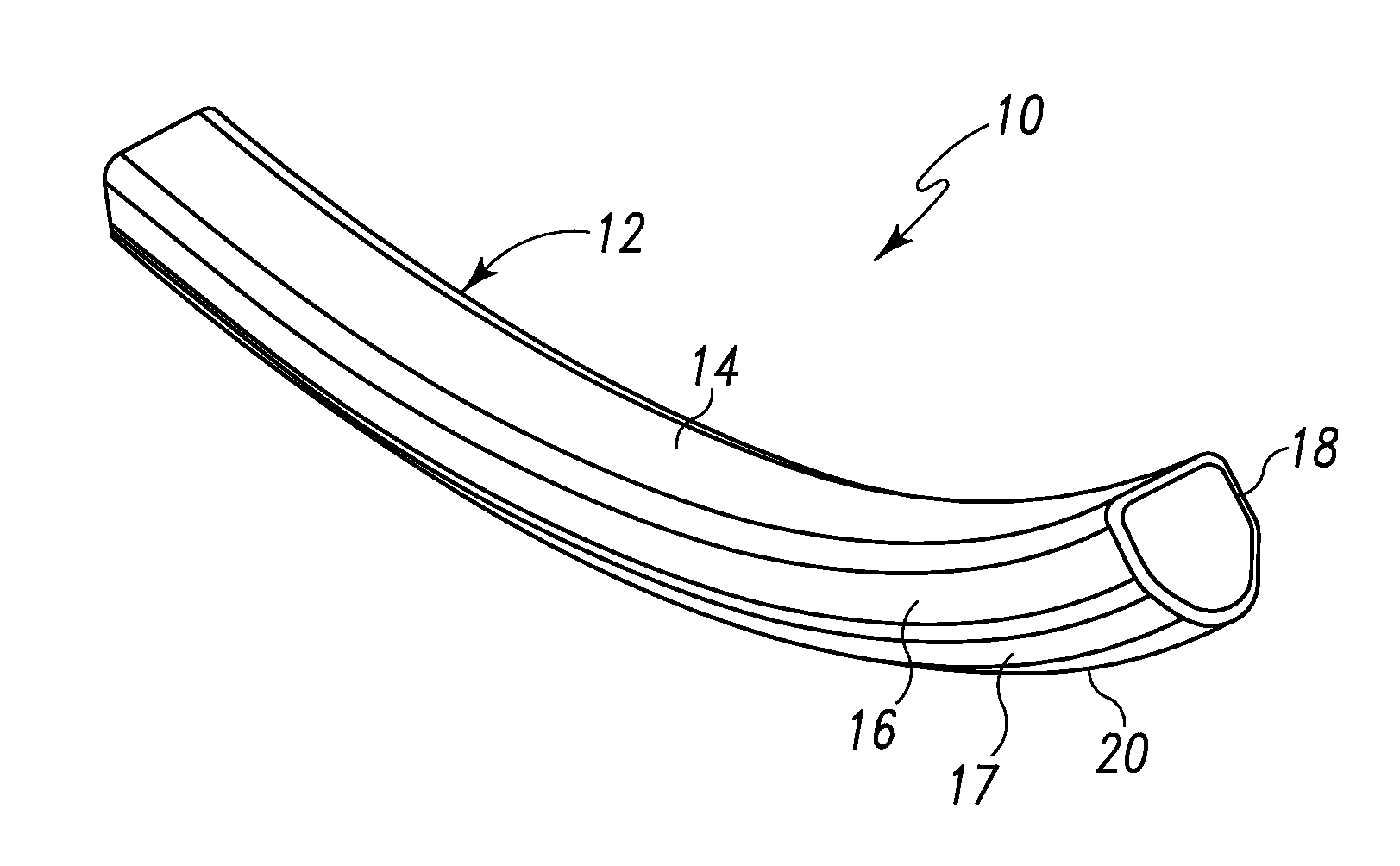
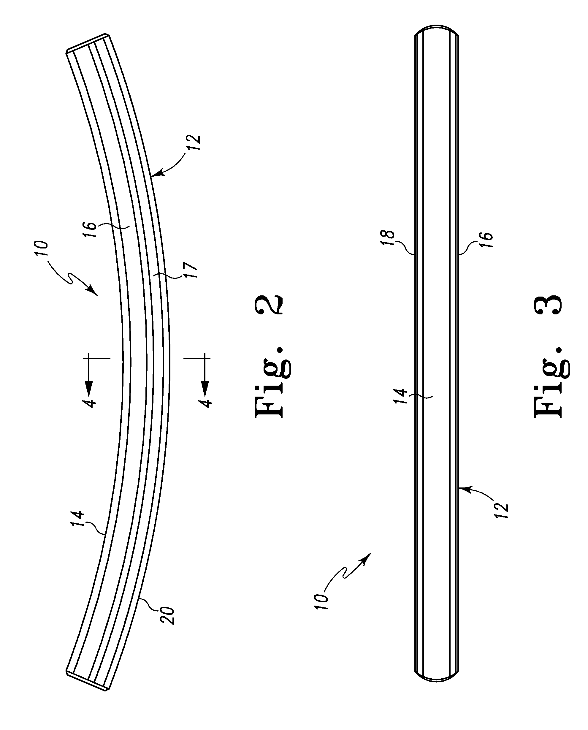
[0028]Referring to FIGS. 1-4 there is depicted an exemplary embodiment of a spine implant formed as a spine or spinal rod generally designated 10 fashioned in accordance with the principles of the present invention. The spinal rod 10 is made from a biocompatible material such as PEEK, titanium or stainless steel, but is preferably made from PEEK. However, other biocompatible materials or compounds may be used such as a polymer, plastic, metal alloy, composite or the like. The spinal rod 10 has a cross-section defining angled sides that cooperate with a spinal rod opening of a spinal rod holder to positively seat the spinal rod in the spinal rod holder.

[0029]The spinal rod 10 is defined by a body 12 of a particular length. The body 12 has an essentially pentagonal or V-shaped cross-section such as is best seen in FIG. 4. The body 12 thus defines several sides or side surfaces. Particularly, the body 12 has a top or posterior side / side surface 14, a first lateral side / side surface 16,...


PUM


Abstract

A spine or spinal rod has a cross-section defining angled sides that cooperate with a spinal rod opening of a spinal rod holder. In one form, the spine rod has an essentially pentagonal cross-section that thus essentially defines angled sides or side surfaces that interact with the spinal rod holder opening to positively seat the spine rod into the spinal rod holder and prevent spine rod from rotation. In the pentagonal cross-section form, the spine rod has a top or posterior side / side surface, a bottom or anterior side / side surface, a first lateral side / side surface, a second lateral side / side surface, a first angled sub-lateral side / side surface and a second angled sub-lateral side / side surface. The first and second angled sub-lateral sides / side surfaces provide contact with angled sides of the spine rod holder opening. In another form, the spine rod has an essentially V-shaped cross-section that defines sides / side surfaces that interact with the spinal rod holder opening. Preferably, but not necessarily, the spine rod is formed of PEEK. Other bio-compatible materials, however, may be used.

Description

RELATED APPLICATIONS[0001]This patent application claims the benefit of and / or priority to U.S. Provisional Patent Application Ser. No. 61 / 095,650 filed Sep. 10, 2008, entitled “V-Shaped Spinal Rod” the entire contents of which is specifically incorporated herein by this reference.BACKGROUND OF THE INVENTION[0002]1. Field of the Invention[0003]The present invention relates to devices for the stabilization of the spinal column and, more particularly, to spine or spinal rods used in the stabilization of the spinal column.[0004]2. Background Information[0005]A significant portion of the population suffers from spinal problems. Such spinal problems may be attributable to disease, trauma and / or other event. In the case of degenerative disc disease, spinal trauma and the like, such conditions are often painful and / or physically deforming. Depending on the situation, the pain and complications caused by these conditions may require that one or more vertebra, facet joints, and / or interverte...

Claims


Application Information

Patent Timeline
IPC IPC(8): A61B17/70
CPCA61B17/701A61B17/7083A61B17/7032A61B17/7011
Inventor BUTLER, MICHAEL S.
Owner LIFE SPINE
Learn More