
Angularly Stable Fixation Of An Implant

Active Publication Date: 2010-08-19
WOODWELDING +1
View PDF35 Cites 7 Cited by
  • Summary
  • Abstract
  • Description
  • Claims
  • Application Information

AI Technical Summary

Benefits of technology

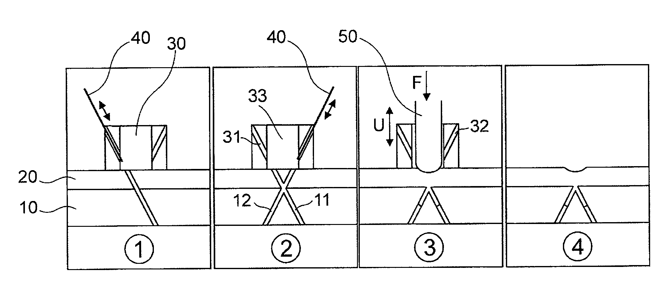
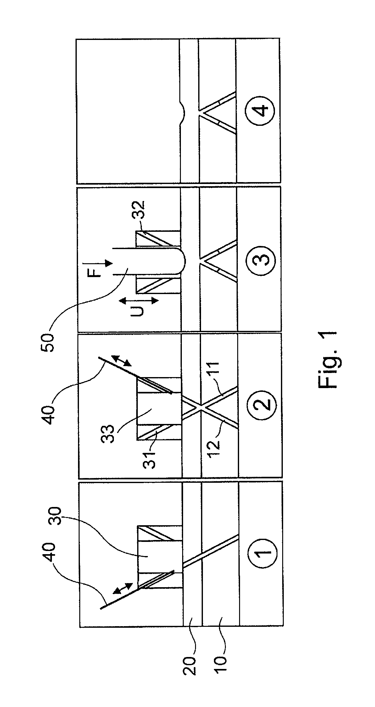
[0010]According to an exemplary embodiment the present invention provides a system that includes a plate having an opening formed therein. The opening is rotationally non-symmetric. The system also includes a drill. The drill is adopted to form the opening and a hole in a bone adjacent the plate. The system further includes a pin insertable in the opening. A sonotrode is also included in the system. The sonotrode is adapted to apply energy to the pin so as to melt at least a portion of the pin thereby attaching the pin in the bone and to the plate such that rotational movement of the plate is prevented.
[0014]Another method of fracture fixation teaches placing a plate on a bone and forming at least one opening in the plate and the bone. The opening is rotationally non-symmetric. A pin is inserted in the opening and energy is applied to the pin to melt at least a portion of the pin thereby attaching the pin in the bone and to the plate such that rotational movement of the plate is prevented.

Problems solved by technology

It has turned out, however, that fixed bone parts do not always grow together as desired.
In addition, the conventional invasive methods of fracture fixation are accompanied by relatively high trauma and loss of blood.
However, these fixing plates cannot be fastened ideally.

Method used


Image

  • Angularly Stable Fixation Of An Implant
  • Angularly Stable Fixation Of An Implant
  • Angularly Stable Fixation Of An Implant

Examples


third embodiment

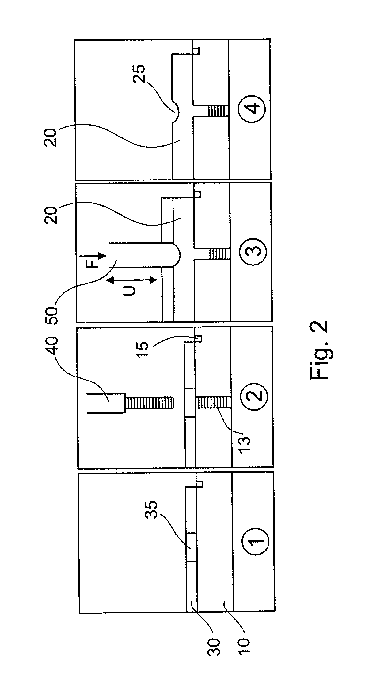
[0034]FIG. 3 shows a third exemplary embodiment that illustrates the method according to the invention. The third embodiment uses pre-formed implant plate 20. The plate 20 has the geometry that also fulfils the functions of the polymeric pins of other exemplary embodiments. The implant plate 20 of the third exemplary embodiment comprises protrusions 22 that are sized to be slid into holes 13 in the bone 10. The location of the protrusions 22 in the implant plate 20 requires a very exact and corresponding positioning of thread holes 13 in the bone 10. This can be managed, for example, by means of a jig 30b.

[0035]As shown in frame 1 in FIG. 3, first the jig 30 is placed on the bone 10. Next, threaded openings 13 are formed in the bone 10 using screw tap 40. The holes 35 in the jig 30b are used to guide screw tap 40 during formation of openings 13. Next, the implant plate 20 is placed on bone 10 such that protrusions 22 project into each drilled hole (i.e., opening) 13. The implant ma...

sixth embodiment

[0039]The sixth exemplary embodiment of the invention is shown in FIG. 6. This method practiced using the sixth embodiment is similar to the method in accordance with the fifth exemplary embodiment. The difference here is that in place of the threaded hole 13, a through hole 14 is formed in the bone 10. The through hole 14 is drilled through the implant plate 20 and cortical portion of the bone 10. The simple procedure for preparing of the bone 10 and the implant plate 20 represents a principal benefit of this solution. This simple procedure of making a smooth hole 14 is performed using a drill 40 as shown in frame 1 in FIG. 6. Next the surgeon inserts a polymeric pin 60 in the hole 14 and pushes it by means of a sonotrode 50. The diameter of the polymeric pin 60 is slightly greater than that of the hole 14 in the bone 10. The diameter difference ideally is about 0.1 to 0.2 mm.

[0040]The application of the ultrasound energy via the sonotrode 50 melts the material of the pin 60 where ...

seventh embodiment

[0041]The seventh exemplary embodiment of the invention is shown in FIG. 7. In the seventh embodiment, a plug 60 is used instead of a polymeric pin or a screw of the previous embodiments. As shown in frame 1 in FIG. 7, a hole 14 is formed into the implant plate 20 and the bone 10 simultaneously. A drill 40 is used to form the hole 14. A plug 60 is inserted in hole 14 as shown in frame 2 in FIG. 7. At first, latches 63 which are formed at the leading end of the plug 60 are pressed against the shaft 64 of the plug. As soon as the leading edge has penetrated through the cortical portion of the bone 10 into the cancellous bone, the latches 63 expand away from the shaft 64 and anchor the plug 60 in the bone 10.

[0042]As illustrated in frame 3 in FIG. 7, the back end of the plug 60 can then be liquefied by subjecting it to the ultrasonic energy via the sonotrode 50 and thereby welding it to the implant material. The result is a snap-in connection of the plate 20 with the cortical part of b...


PUM


Abstract

A system and method of angularly stable fixation of an implant on a bone includes the steps of making at least one hole in the bone by means of a bone drill. An implant is placed on the bone in a desired position and joining the implant with the bone, such that the implant is prevented from rotation about its attachment point. A system is provided for use in the above described method. The system comprises a bone drill, an implant and a sonotrode for angularly stable fixation of the implant on the bone. The system can further comprise a joining element to join the implant with the bone.

Description

CROSS REFERENCE TO RELATED APPLICATION[0001]The present application is a national phase entry under 35 U.S.C. §371 of International Application No. PCT / EP2007 / 008130, filed Sep. 18, 2007, published in English. The disclosure of said application is incorporated by reference herein.BACKGROUND OF THE INVENTION[0002]1. Field of the Invention[0003]The invention relates to a system and method of fixation of an implant to a bone. The invention particularly relates to a system and method of angularly stable fixation of an implant to a bone.[0004]2. Brief Description of the Prior Art[0005]It is generally known that fractures are treated by fixation of the broken bones. The individual fragments of the bone are lined up to each other so that the separated parts can grow together again. It is necessary that the parts remain relatively stable with respect to each other over a time period to allow the healing. It is possible in many cases to fix the fragments of the fractured bone via a rigid cas...

Claims


Application Information

Patent Timeline
IPC IPC(8): A61B17/80A61B17/58A61B17/00
CPCA61B17/00491A61B17/686A61B17/80A61B17/809A61B17/866A61B17/8822A61B17/808
Inventor SONNTAG, ROBERTDORAWA, KLAUSZANDER, NILS
Owner WOODWELDING
Learn More