
Printable cover systems for articles

a technology for printing covers and articles, applied in the direction of identification means, instruments, seals, etc., can solve the problems of difficult alignment of labels relative to optical disks, affecting the integrity of adhesives, and exposed adhesive coatings

Inactive Publication Date: 2006-02-23
HEWLETT PACKARD DEV CO LP
View PDF18 Cites 39 Cited by
  • Summary
  • Abstract
  • Description
  • Claims
  • Application Information

AI Technical Summary

Benefits of technology

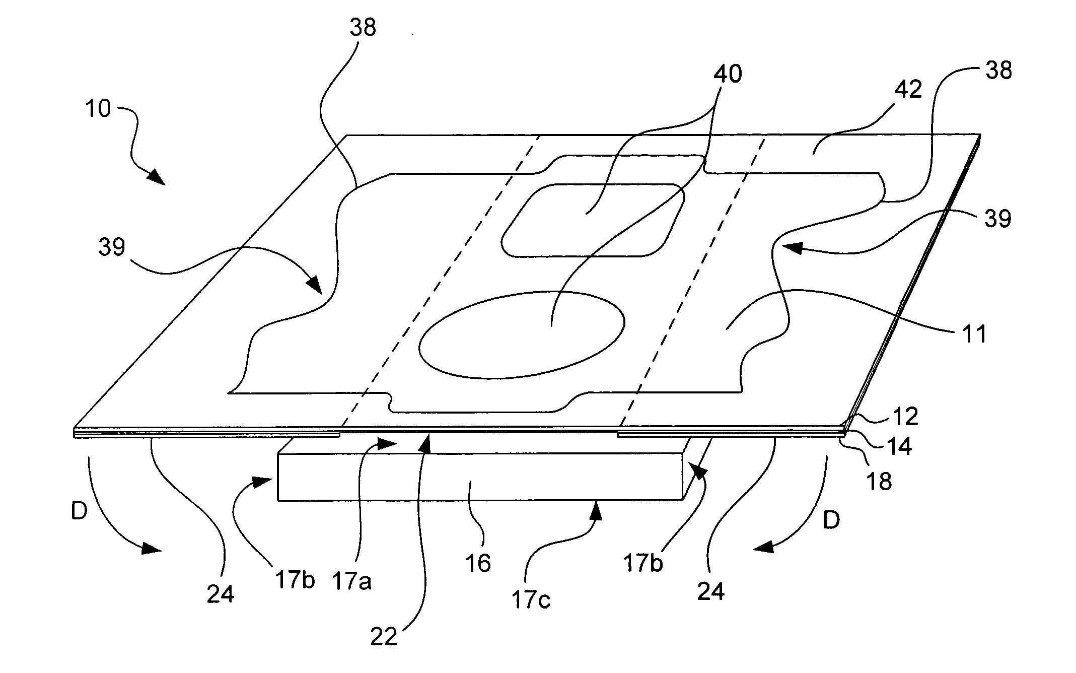
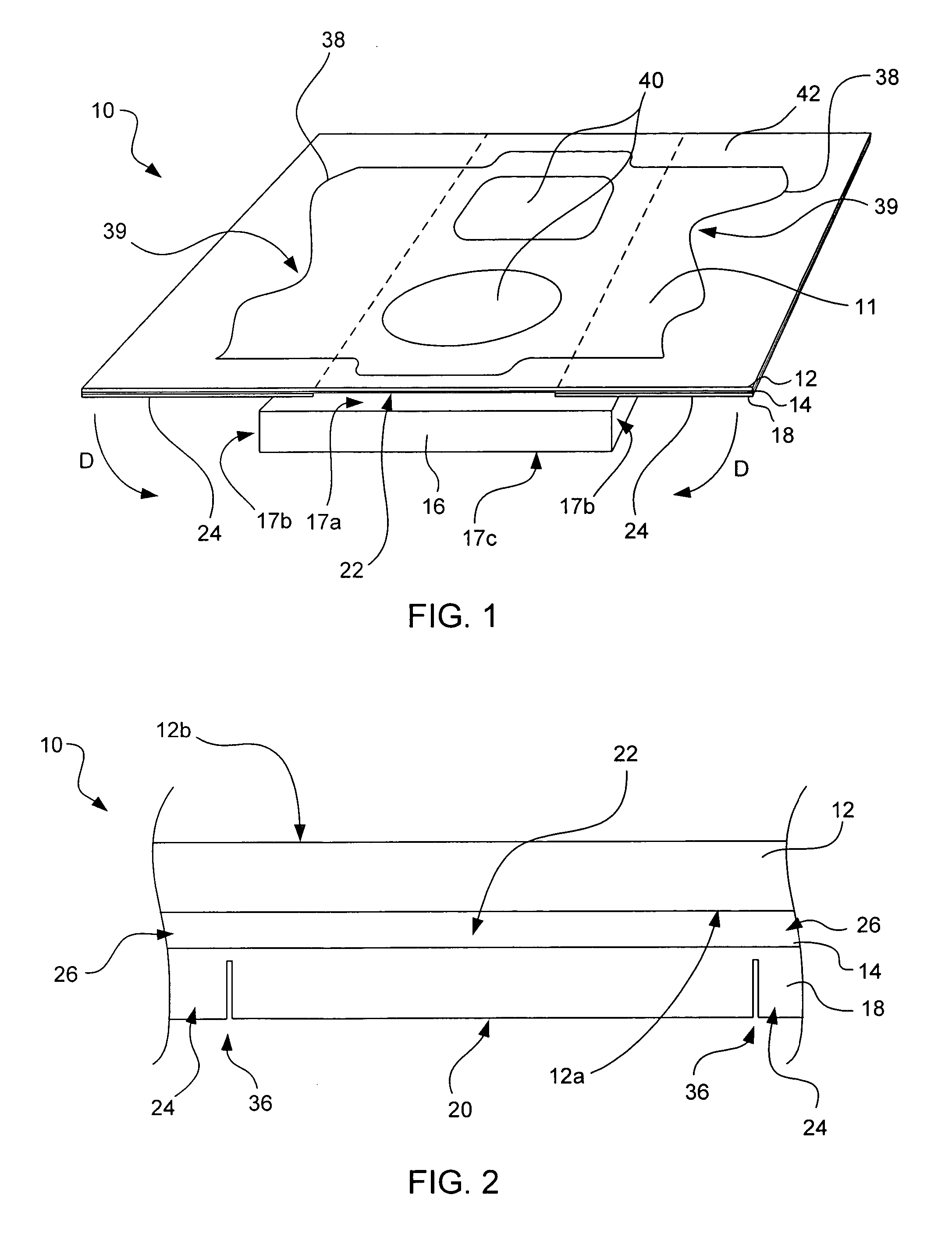
[0007] It has been recognized that it would be advantageous to develop a cover system that allows a consumer to attach a label to an article while avoiding contact with adhesive between the label and the article. In addition, it has been recognized that it would be advantageous to develop a cover system for articles that allows consumers to cover the article with a printable label without obscuring important information displayed on surfaces of the article, including the back surface of the article where serial numbers, model numbers, and other important branding information is typically present.

Problems solved by technology

While relatively simple to use, such labels have proved disadvantageous in that once the backing is removed from the label, the entire adhesive coating is exposed and a consumer must attempt to properly align the label on the optical disk while the consumer's fingers are in contact with the adhesive coating.
Contact between the consumer's fingers and the adhesive can compromise the integrity of the adhesive and can also make properly aligning the label relative to the optical disk difficult.
While such overlays have met with some commercial success, they have suffered from many of the problems inherent in printable optical disk covers.
Contact with the adhesive not only results in difficulty aligning the overly on the article, but the integrity of the adhesive can be compromised by dirt or oil on the user's fingers.

Method used


Image

  • Printable cover systems for articles
  • Printable cover systems for articles
  • Printable cover systems for articles

Examples


Embodiment Construction

)

[0018] Before particular embodiments of the present invention are disclosed and described, it is to be understood that this invention is not limited to the particular process and materials disclosed herein as such may vary to some degree. It is also to be understood that the terminology used herein is used for the purpose of describing particular embodiments only and is not intended to be limiting, as the scope of the present invention will be defined only by the appended claims and equivalents thereof.

[0019] In describing and claiming the present invention, the following terminology will be used:

[0020] The singular forms “a,”“an,” and “the” include plural referents unless the context clearly dictates otherwise.

[0021] As used herein, the term “printed image” is to be understood to refer to an image applied by a printer that can include a variety of printed material including textual material, pictorial material, iconograchical material, etc., and various combinations thereof. A ...


PUM

PropertyMeasurementUnit
adhesiveaaaaaaaaaa
sizeaaaaaaaaaa
cohesive strengthaaaaaaaaaa

Abstract

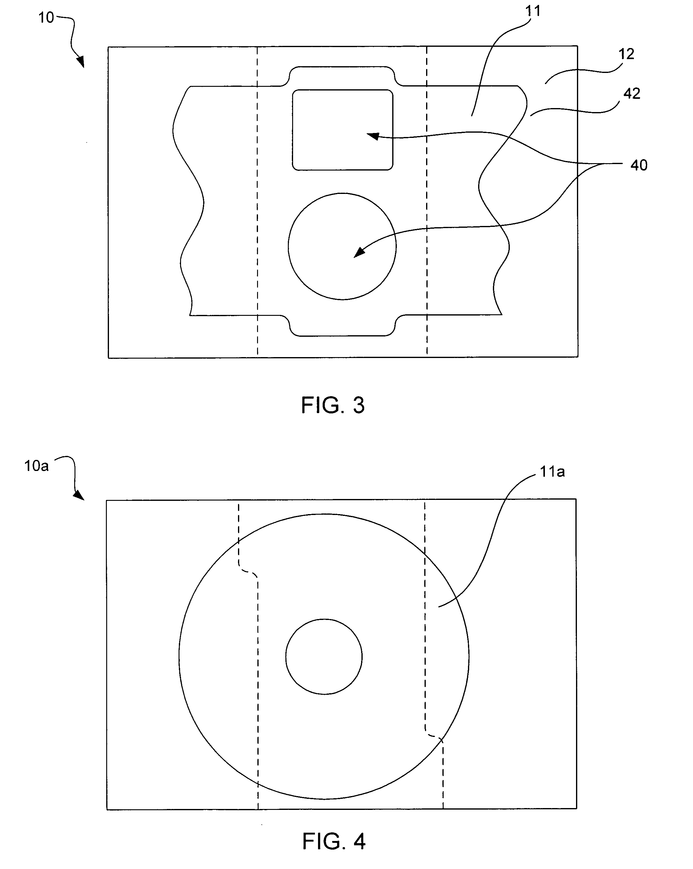
A printable label assembly includes a printable label having an adhesive coating applied to a first surface thereof to facilitate attachment of the label to an article. The label is configured to receive a printed image on a second surface thereof. A removable backing is releasably attached to the adhesive coating and has at least three sections: a removable primary section releasably attached to a central portion of the adhesive coating of the label and being configured to be removed from the central portion to expose the central portion for attachment to the article; and a pair of removable handle sections releasably attached to outward portions of the adhesive coating of the label, the handle sections being configured to remain on the adhesive coating of the label after removal of the primary section to provide at least two handling points for manipulation by a user to assist the user in applying the label to the article.

Description

FIELD OF THE INVENTION [0001] The present invention relates generally to printable covers and cover systems for articles. BACKGROUND OF THE INVENTION [0002] Many consumers desire to apply labels or covers to articles in order to display information relating to the article or to provide an enhanced, decorative appearance to the article. For example, with the advent of writable optical disks, such as CD- and DVD-type optical disks, many consumers wish to apply information to a once-blank optical disk that lists or describes the files subsequently written to the optical disk. While it is generally possible to simply mark directly on the optical disk with a pen or other marking tool, many consumers would rather apply information to the optical disk in a more “finished” or professional manner. In addition, many consumers wish to add decorative features when applying information to an optical disk, such as artwork, photos, colorful highlights, etc. [0003] Printable labels have been develo...

Claims


Application Information

Patent Timeline
Patent Type & Authority Applications(United States)
IPC IPC(8): B41F33/00
CPCG09F3/0288Y10T428/14G11B23/40G09F3/10
Inventor TRIGG, LARRY E.LUCENTE, SAMJOHNSON, ALLISONBRADLEY, PAUL E.GUPTA, ARVIND KUMARJOHNSON, KARA WHITNEYWIESER, MATTHIASADAMS, MATTHEW ROBERT
Owner HEWLETT PACKARD DEV CO LP
Learn More