Door unit

a technology for doors and windows, applied in the field of doors, can solve the problems of one member shifting relative to the other, and achieve the effects of preventing noise generation, improving the design flexibility of the door surface, and good condition

Inactive Publication Date: 2006-02-23
NIFCO INC +1
View PDF18 Cites 37 Cited by
  • Summary
  • Abstract
  • Description
  • Claims
  • Application Information

AI Technical Summary

Benefits of technology

[0009] It is particularly preferable to spring-bias said sheet member (12) with a spring means (18 / 24) so as to receive tension in the sliding direction at all times. Moreover, the aforementioned sheet member (12) may preferably be guided by a separate guide groove (6a) disposed independent of the aforementioned guide groove (6b) for guiding the door body (11). The spacing between the guides (6a and 6b) is preferably set so as to prevent the generation of noise that would otherwise be caused by the door body (11) and the sheet member (12) rubbing against each other, at least in the curved section of the opening (2c), when they are opened or closed.
[0010] In accordance with the present invention, the design surface for the uneven bendable slatted door body can be formed with a separate sheet member, and thus the sheet member enables the creation of a design surface without any restriction. For the flexible sheet member, an aluminum vapor-deposited sheet, for example, can be used. This significantly increases the options for the material to be employed for the design surface of the shutter door unit, and improves the design flexibility of the door surface.
[0011] Moreover, spring-biasing the sheet member in the sliding direction can prevent slack that otherwise would occur in the flexible sheet member. Thus, the design surface can be maintained in a good condition even when the flexible sheet member is disposed separately from the door body. By guiding the door body and the sheet member with separate guide grooves, in particular, the spacing between the two can be secured. This can prevent the design pattern of the relatively stiff slatted door body from appearing through the sheet member in the case in which the sheet member is thin. When the ends of the door body and the sheet member are connected on the same side, moreover, the difference in the peripheral distances of the guide groove may cause one member to shift relative to the other in the curved section. By setting the spacing between the two so that they won't rub against each other, the generation of a rustling noise or friction can be prevented.

Problems solved by technology

When the ends of the door body and the sheet member are connected on the same side, moreover, the difference in the peripheral distances of the guide groove may cause one member to shift relative to the other in the curved section.

Method used


Image

  • Door unit
  • Door unit
  • Door unit

Examples


Embodiment Construction

[0026] In the following, embodiments of the present invention will be explained with reference to the drawings.

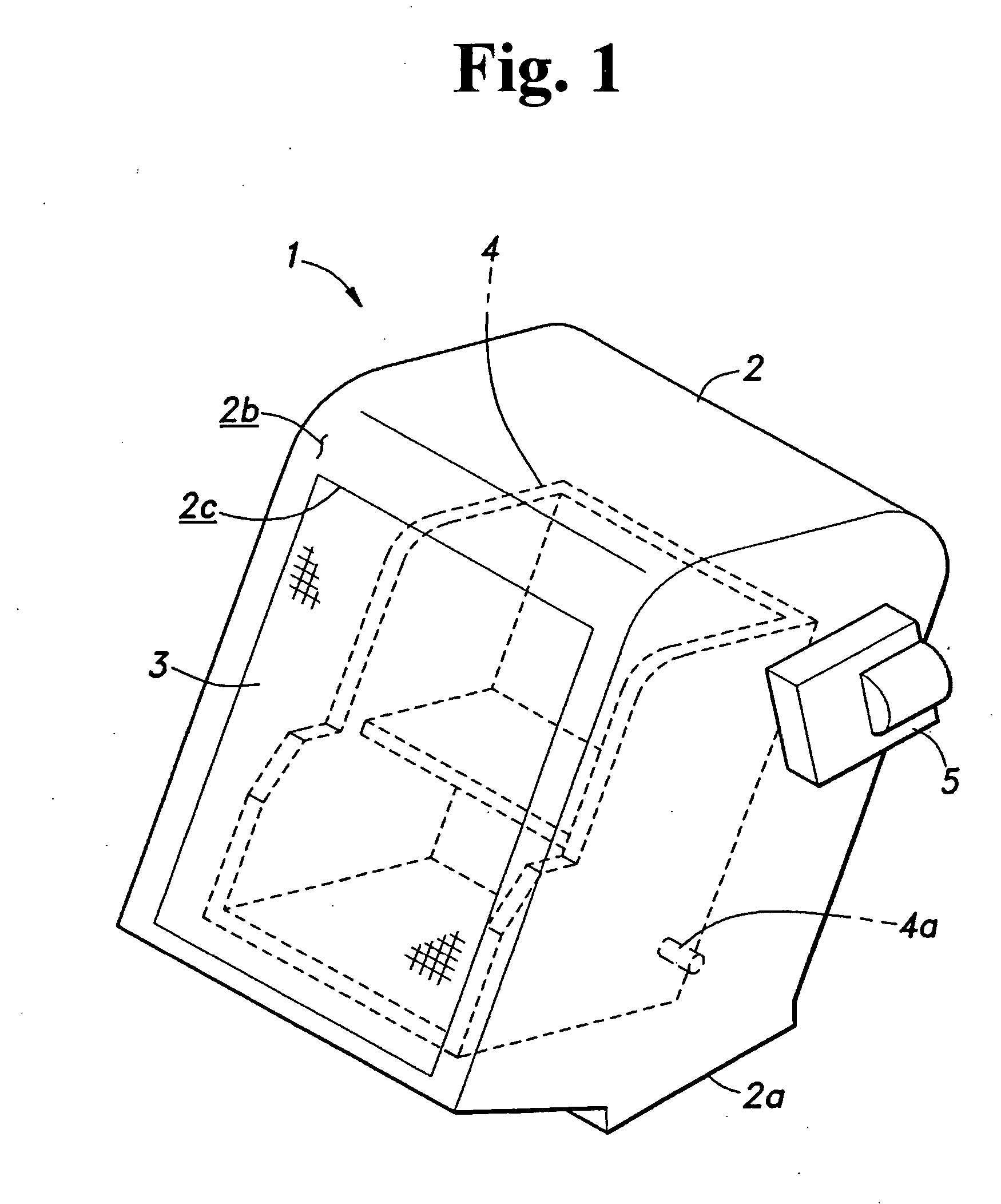
[0027]FIG. 1 is a full perspective view of the storage box 1 to which the present invention is applied, installed, for example, in the cabin of a vehicle. In the figure, the leg section 2a formed in the bottom surface of the rectangular box-shaped case 2 is screw mounted to a vehicle body frame in the appropriate location (not shown).

[0028] In the case 2, a rectangular opening 2c is formed in the surface 2b that is flush with the interior member of the vehicle cabin, and a door 3 is disposed to place the opening 2c in two states, i.e., the fully closed and fully opened states. In the interior of the case 2, an inner case 4 shaped so as to store CDs, for example, is installed. The inner case 4 is slidably supported by the guide rail (not shown) so as to assume two positions: an inner receiving position and an accessible position that is slightly projected from the opening ...


PUM


Abstract

A door unit for selectively opening and closing an opening in an object includes a door having a bendable slatted door body and a flexible sheet member positioned over the door body. Guide grooves in the object slidably guide at least the door body, and the respective ends of the door body and the sheet member are connected on one end in the sliding direction. By setting an appropriate spacing between the guide grooves, the generation of noise that would otherwise be caused by the door body and the sheet member rubbing against each other when they are opened or closed, is avoided. The use of the separate sheet member also significantly increases the options for the material to be employed for the design surface of the door unit.

Description

BACKGROUND OF THE INVENTION AND RELATED ART STATEMENT [0001] The present invention relates to a door unit for selectively opening and closing the opening of an object having at least one open surface. [0002] As a conventional door unit for opening and closing the opening of an object, a unit that can be employed in a center console of a vehicle, for example, for opening and closing the opening of a storage unit disposed therein is available. In the case wherein the layout does not permit the arrangement of a housing section for the door in the extension of the open surface of the center console due to a curved section that exists in the middle, a bendable slatted shutter is employed for the door. [0003] Patent reference 1: Japanese Patent Laid-open Publication No. 2003-90486 [0004] In the shutter described above, both side edges thereof are guided along the guide grooves disposed in the storage unit casing, and the shutter is formed of a synthetic resin material in a configuration t...

Claims


Application Information

Patent Timeline
Patent Type & Authority Applications(United States)
IPC IPC(8): E04F10/00
CPCB60R7/04B60R2011/0094B60R2011/0075B60R11/00
Inventor ICHIMARU, TAKAHIDEMATSUI, TORUSHIONO, MASAMITSU
Owner NIFCO INC
Why Eureka
Try Eureka