
Internal mix air atomizing nozzle assembly

Active Publication Date: 2006-02-23
SPRAYING SYST
View PDF3 Cites 15 Cited by
  • Summary
  • Abstract
  • Description
  • Claims
  • Application Information

AI Technical Summary

Benefits of technology

[0005] It is an object of the invention to provide an internal-mix spray nozzle assembly adapted for more efficiently generating air-atomized liquid spray discharges.
[0008] Still another object is to provide an internal mix air atomizing spray nozzle assembly of the foregoing type which is adapted for finely atomizing the liquid, while preventing the accumulation of liquid within the housing and resulting undesirable drippage from the nozzle during spray operations.
[0009] A yet further object is to provide a spray nozzle assembly of the above kind that is relatively simple in construction and economical to manufacture and operate.

Problems solved by technology

Pressurized air sources available in customer plants sometimes are inadequate to enable such spray nozzles to be operated with optimum liquid atomization, particularly in spraying systems which involve a large number of such air atomizing nozzles.

Method used


Image

  • Internal mix air atomizing nozzle assembly
  • Internal mix air atomizing nozzle assembly

Examples


Embodiment Construction

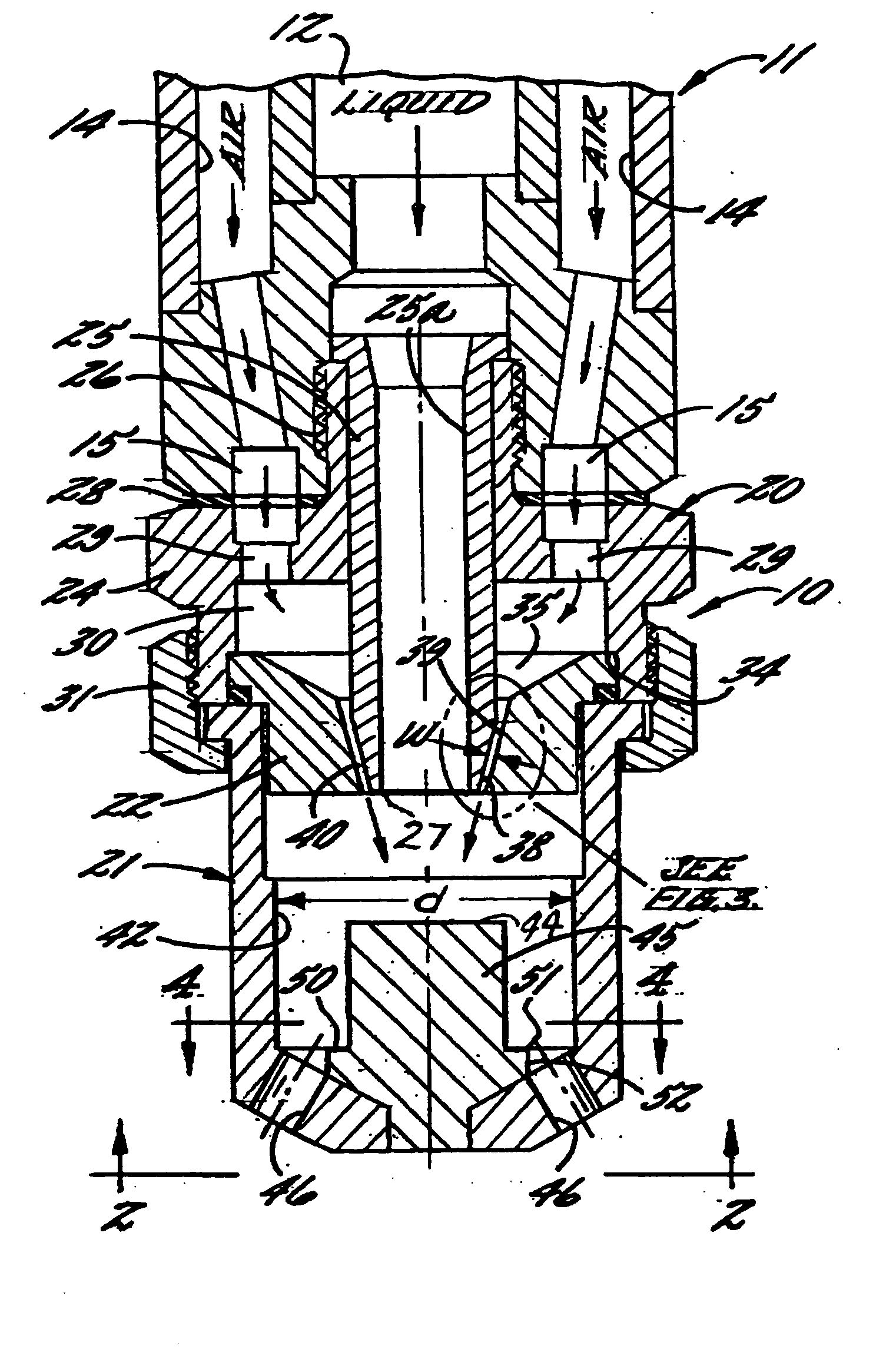
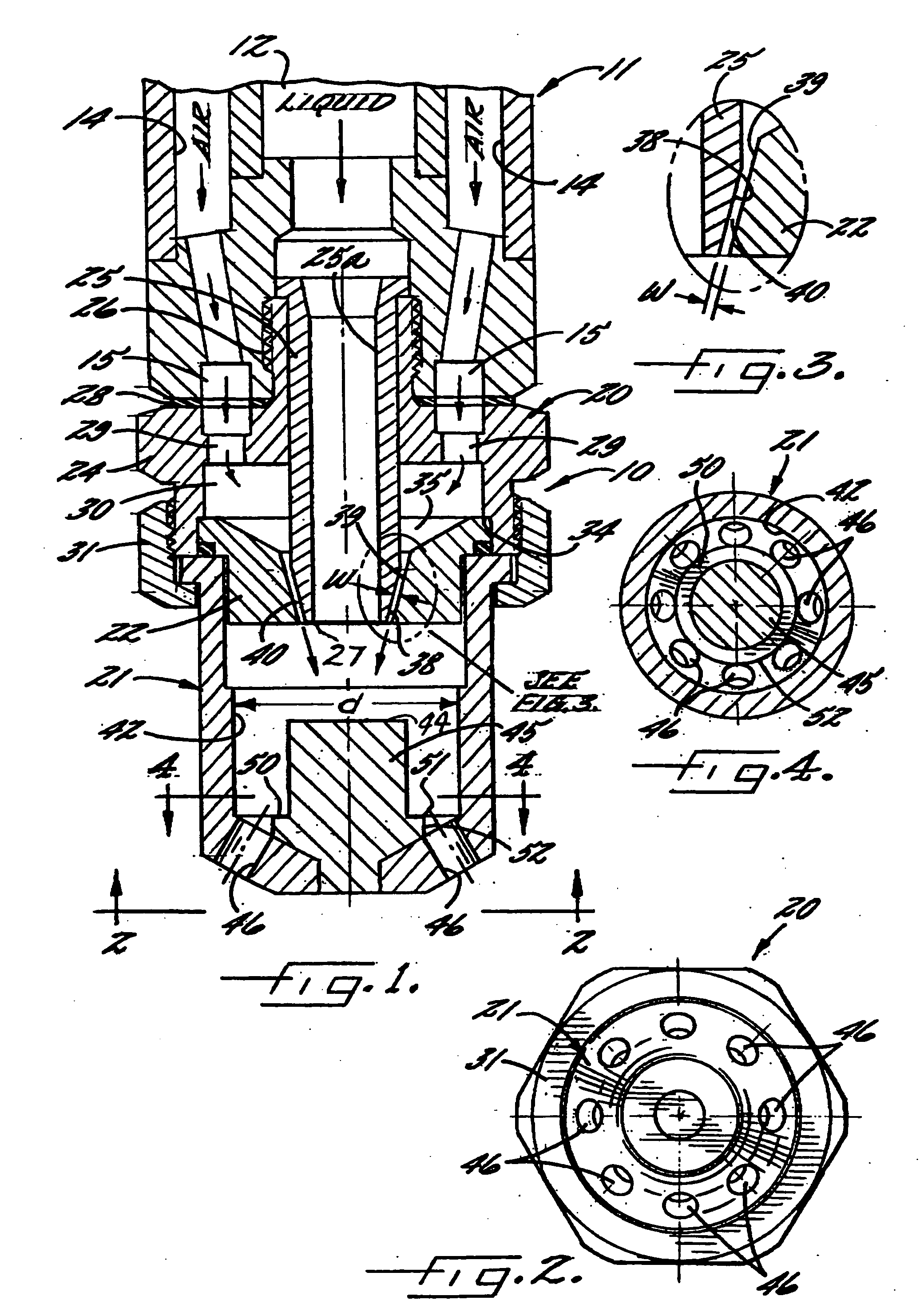
[0016] Referring now more particularly to the drawings, there is shown an illustrative internal-mix, air-atomizing spray nozzle assembly 10 in accordance with the invention connected to a conventional fluid supply manifold 11. The fluid supply manifold 11 in this case includes a central pressurized liquid supply passage 12 and a plurality of pressurized air supply passages 14 in surrounding relation to the liquid supply passage 12. The air passages 14 in this instance communicate with an annular manifold air passage 15 at a downstream end of the fluid supply manifold 11.

[0017] The illustrated spray nozzle assembly 10 basically comprises a nozzle body 20, a downstream spray tip 21, and an air guide 22 interposed between the nozzle body 20 and spray tip 21. The nozzle body 20 in this case is in the form of a multipart fluid supply subassembly comprising an outer annular body member 24 and an inner axial liquid supply tube 25 fixed therein which defines a liquid discharge orifice 27. ...


PUM


Abstract

An internal mix spray nozzle assembly adapted for operation with lesser pressurized air requirements. The spray nozzle assembly includes a liquid passage for directing a liquid flow stream against an impingement pin, and an air guide is provided for forming an annular pressurized air passage about the liquid flow stream for striking and atomizing a laterally spreading dispersion of liquid from the impingement surface. For enhancing liquid atomization, the air guide defines a relatively narrow width air flow opening for substantially accelerating and increasing the pressure of the atomizing air stream, and the impingement pin is formed with a relatively large primary impinging surface and a parallel downstream secondary impingement surface that facilitates further liquid particle breakdown and prevents the accumulation of liquids about the bottom of the impingement pin.

Description

CROSS-REFERENCE TO RELATED PATENT APPLICATIONS [0001] This application claims the priority of U.S. provisional application Ser. No. 60 / 603,844, filed Aug. 23, 2004.FIELD OF THE INVENTION [0002] The present invention relates generally to spray nozzles, and more particularly, to internal-mix, air-atomizing spray nozzles of the type in which a liquid flow stream is pre-atomized by pressurized air internally within the nozzle prior to discharge. BACKGROUND OF THE INVENTION [0003] Internal mix air atomizing nozzles are known in the art, such as shown in U.S. Pat. No. 5,732,885 assigned to the same assignee as the present invention, the disclosure of which is incorporated herein by reference. Such air atomizing nozzles are particularly effective for generating and discharging a finely atomized liquid spray at high flow rates. [0004] Pressurized air sources available in customer plants sometimes are inadequate to enable such spray nozzles to be operated with optimum liquid atomization, par...

Claims


Application Information

Patent Timeline
IPC IPC(8): B05B7/06
CPCB05B7/0466B05B7/0892B05B7/0475B05B7/06
Inventor HUFFMAN, DAVID C.EKPENYONG, JOHN E.BARTELL, JOHN W.
Owner SPRAYING SYST
Learn More