DC induction electric motor-generator

a technology of electric motors and generators, applied in the direction of mechanical energy handling, magnetic circuit rotating parts, magnetic circuit shape/form/construction, etc., can solve the problem that the prior art fails to teach the rotation of electromagnetic machines

Active Publication Date: 2006-02-23
CLEARWATER TECH SYST +1
View PDF26 Cites 41 Cited by
  • Summary
  • Abstract
  • Description
  • Claims
  • Application Information

AI Technical Summary

Benefits of technology

[0013] A further objective is to provide such a machine useful as an electric motor.
[0014] A further objective is to provide such a machine useful as an electric generator.
[0015] Other features and advantages of the described apparatus and...

Problems solved by technology

However, the prior art fails to teach a rotating electromagnetic machine that provides electromagnetic fields immersed in mon...

Method used


Image

  • DC induction electric motor-generator
  • DC induction electric motor-generator

Examples


Embodiment Construction

[0019] The above described drawing figures illustrate the described apparatus and its method of use in at least one of its preferred, best mode embodiments, which is further defined in detail in the following description. Those having ordinary skill in the art may be able to make alterations and modifications to what is described herein without departing from its spirit and scope. Therefore, it must be understood that what is illustrated is set forth only for the purposes of example and that it should not be taken as a limitation in the scope of the present apparatus and method of use.

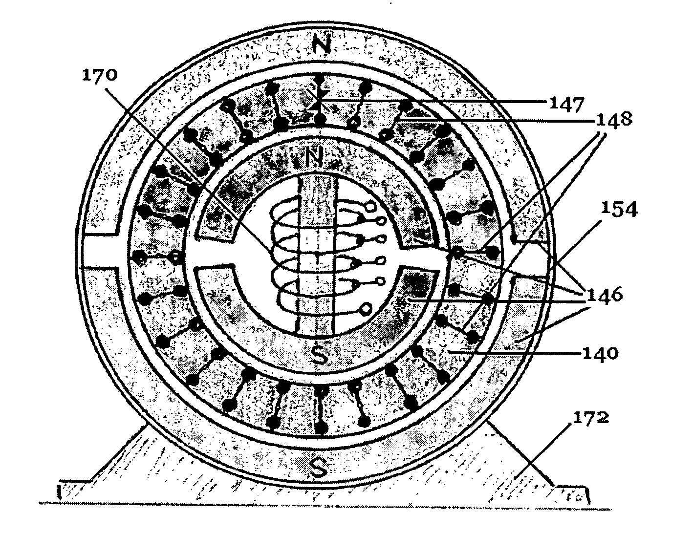
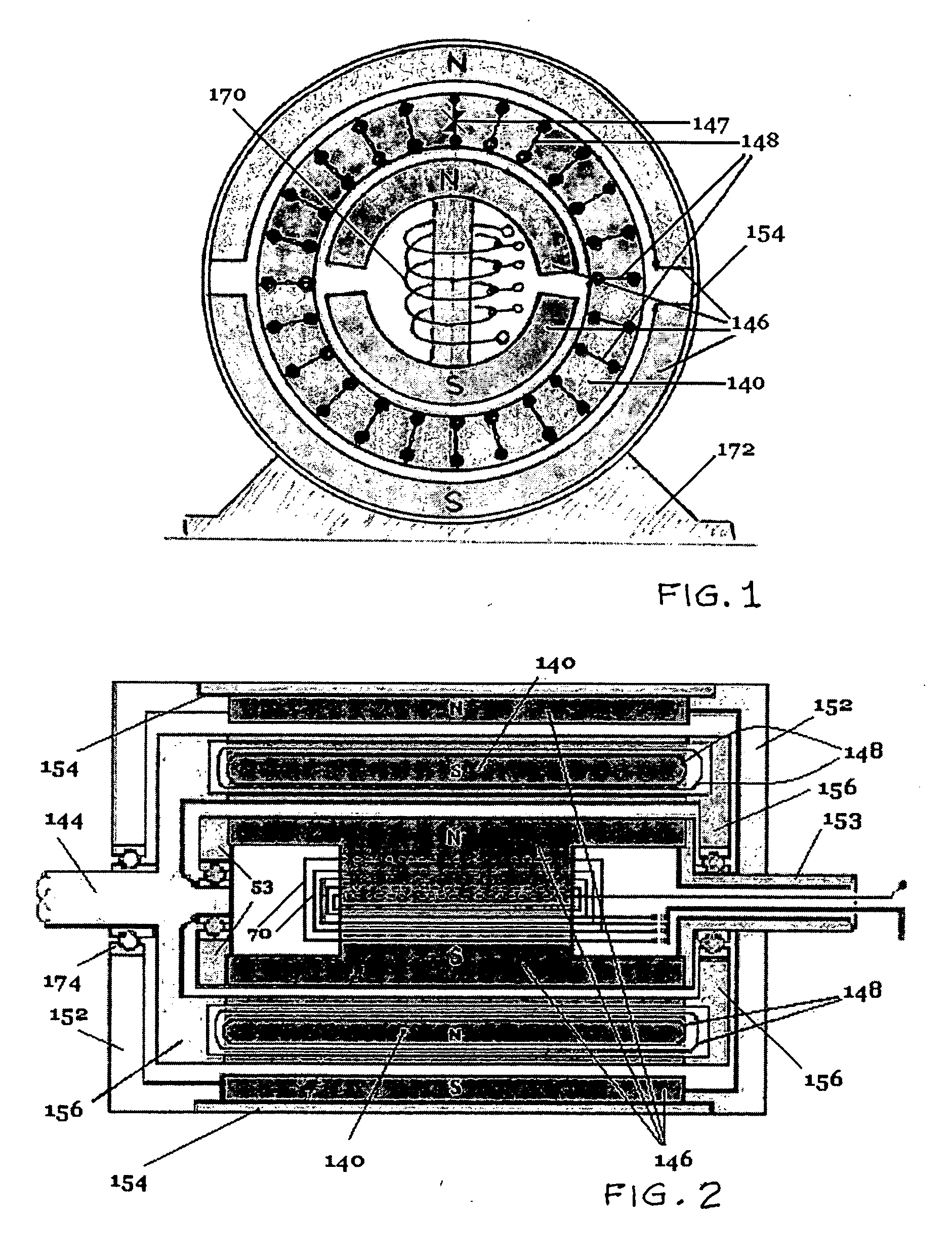
[0020]FIG. 1 is a cross-sectional view of an embodiment of the apparatus defined in U.S. application Ser. No. 11200920 of which the present application is a Continuation-In-Part and which operates under the same principle; in which the linear-toroidal ferromagnetic core 140 has a shorted electric motor-generator solenoid coil 148, and which is a rotating autotransformer rotating between the active per...


PUM


Abstract

An electromagnetic apparatus has a rotating element acting as a transfer bridge between two active energetic suppliers, the rotating element providing a ferromagnetic core with plural solenoid coils having induced electric energy from external permanent magnets; the core transferring energy by induction to the inner stator's wound active permanent magnet, the energy collector and inductor acting as a generator.

Description

RELATED APPLICATIONS [0001] This application claims international priority from a prior filed U.S. Provisional Patent Application having Ser. No. 60 / 603,444 filed with the United States Patent Office on Aug. 20, 2004 and which is copending with this present non-provisional application. U.S. Ser. No. 60 / 603,444 is hereby incorporated herein by reference. This application is a Continuation-In-Part application of a prior filed U.S. Utility patent application having Ser. No. 11200920 and entitled “Monopole Field Electric Motor Generator” filed on Aug. 9, 2005.BACKGROUND [0002] 1. Field of the Present Disclosure [0003] This disclosure relates generally to electric motor-generators and more particularly to a DC rotating electromagnetic machine operating by induction. [0004] 2. Description of Related Art [0005] The following art defines the present state of the field of the apparatus described and claimed herein: [0006] Tu et al, US 2004 / 0135452, discloses a flat rotary electric generator ...

Claims


Application Information

Patent Timeline
IPC IPC(8): H02K16/04H02K7/20
CPCH02K7/20H02K21/04H02K57/006H02K57/00H02K57/003H02K21/38H02K99/00H02K99/10H02K99/20H02K19/38H02K47/14
Inventor BOJIUC, DUMITRU
Owner CLEARWATER TECH SYST
Why Eureka
Try Eureka