
Apparatus and method for striking a fluorescent lamp

a technology of power conversion circuit and fluorescent lamp, which is applied in the direction of instruments, basic electric elements, light sources, etc., can solve the problem of limited power required to generate light, and achieve the effect of efficient processing

Inactive Publication Date: 2006-02-23
MICROSEMI CORP
View PDF14 Cites 39 Cited by
  • Summary
  • Abstract
  • Description
  • Claims
  • Application Information

AI Technical Summary

Benefits of technology

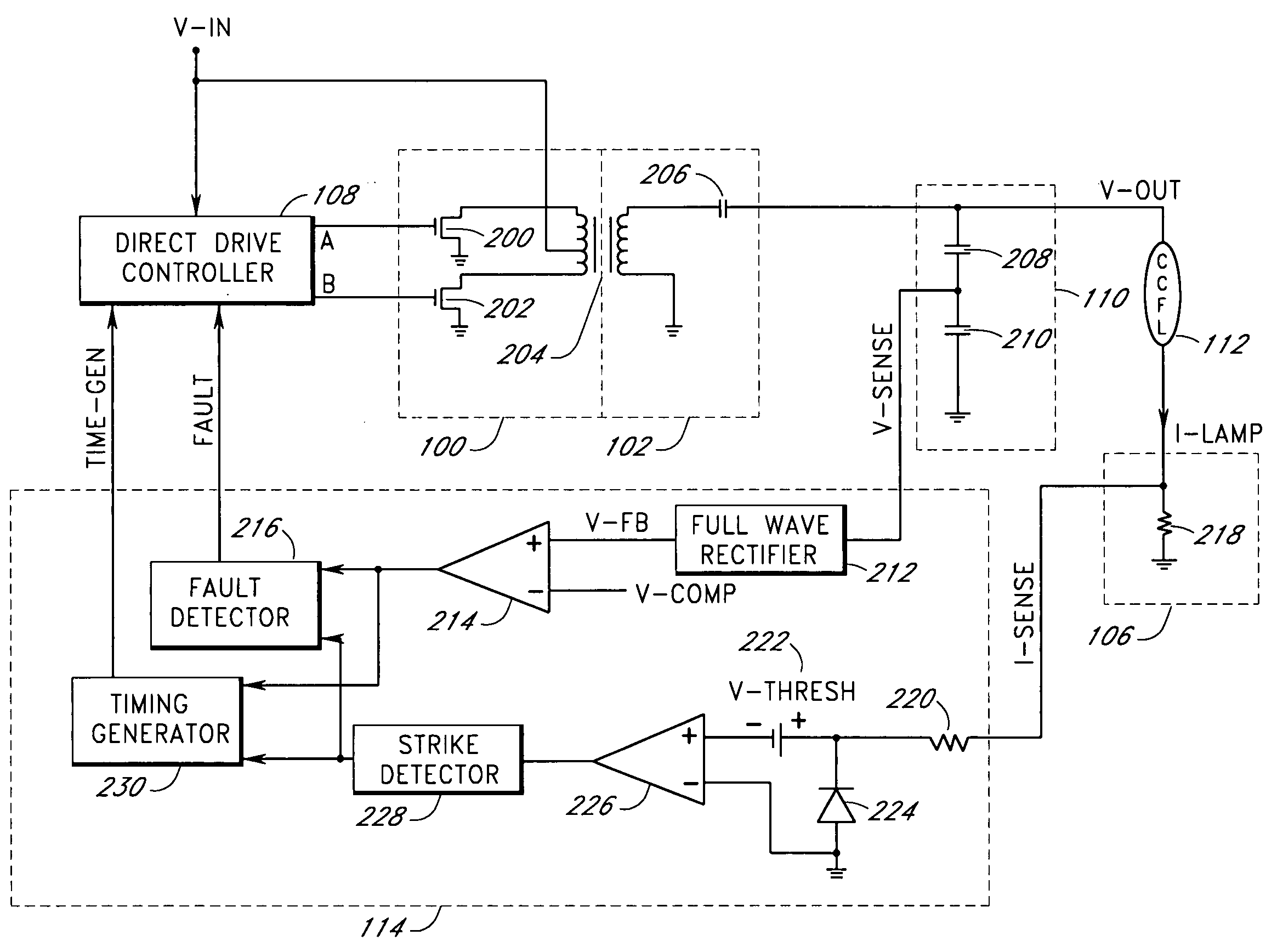
[0009] One aspect of the present invention is a power conversion circuit (or a lamp inverter) with a strike circuit to apply a continuous strike voltage at an output to a fluorescent lamp for efficient ignition of the fluorescent lamp. The strike circuit helps the fluorescent lamp to start (or to strike) in a relatively short time, especially at relatively cold temperatures. The strike circuit maintains the continuous strike voltage at a relatively high level when the power conversion circuit is in an ignition mode (or a striking mode). After the fluorescent lamp strikes, the power conversion circuit enters a normal operating mode and a relatively lower level normal operating voltage is provided at the output to the fluorescent lamp.
[0015] If the strike circuit detects ignition of the CCFL during the frequency sweep, the strike circuit stops the frequency sweep and resets the frequency of the driving signals to the normal operating frequency for normal operations. If the striking frequency is reached before the CCFL ignites during the frequency sweep, the strike circuit locks (or stops sweeping) the frequency of the driving signals. The frequency of the driving signals stays at the striking frequency to continuously apply the striking voltage to the unlighted CCFL. The strike circuit continues to monitor the status of the CCFL and reduces the frequency of the driving signals to the normal operating frequency once the CCFL ignites. The continuous application of the striking voltage advantageously facilitates faster starting of the CCFL.
[0017] In one embodiment, the strike circuit monitors the status of the CCFL by monitoring the lamp current. For example, the absence of lamp current indicates that the CCFL is not ignited. The presence of lamp current with a predefined minimum amplitude and for a predefined minimum duration indicates reliable ignition of the CCFL. The strike circuit can monitor the level of the substantially AC output voltage using a capacitive divider placed across (or in parallel) with the CCFL. The capacitive divider produces a scaled version of the relatively high voltage levels of the substantially AC output voltage for efficient processing by the strike circuit.

Problems solved by technology

Fluorescent lamps are used in a number of applications where light is required but the power required to generate the light is limited.

Method used


Image

  • Apparatus and method for striking a fluorescent lamp
  • Apparatus and method for striking a fluorescent lamp
  • Apparatus and method for striking a fluorescent lamp

Examples


Embodiment Construction

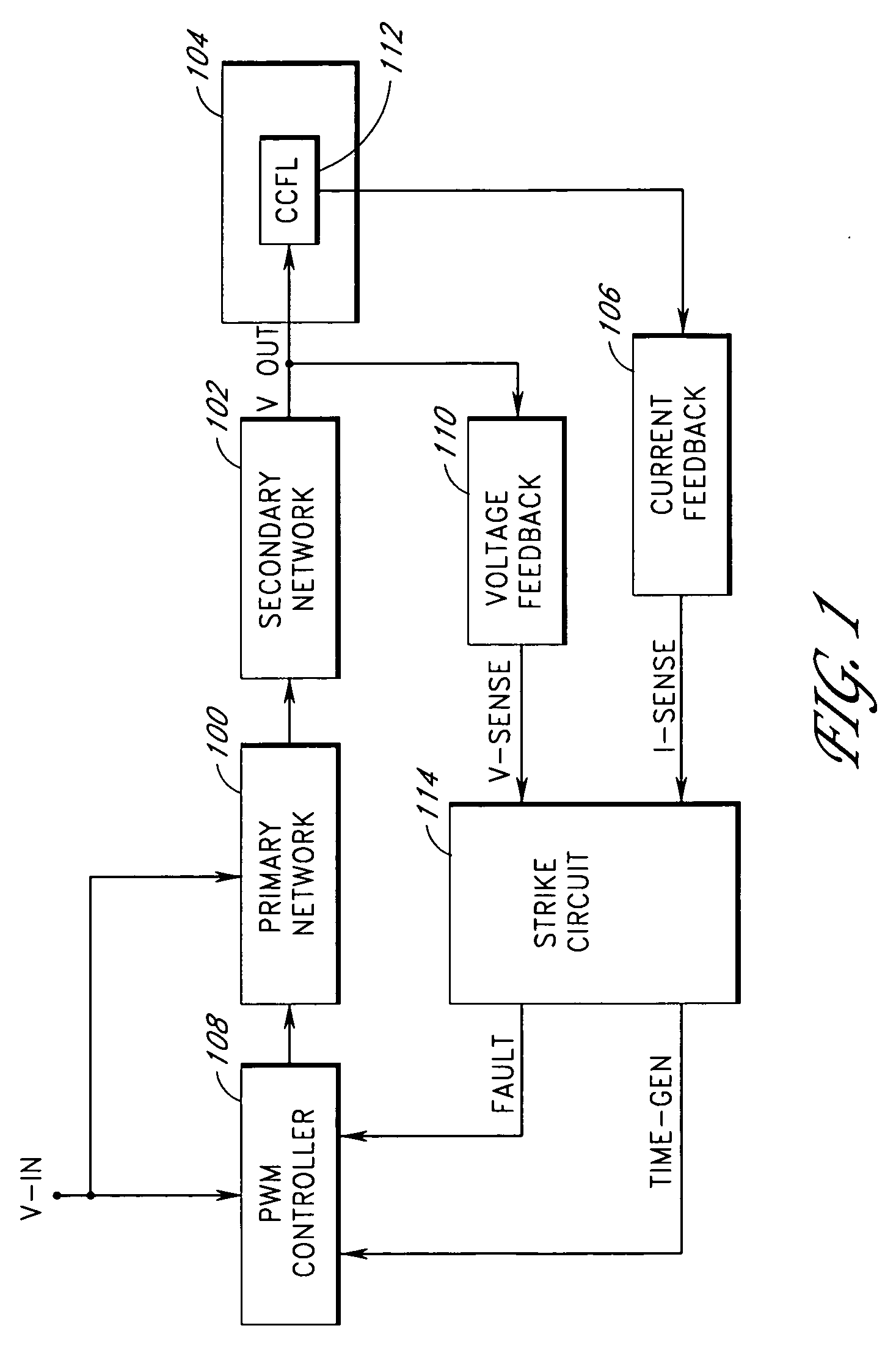
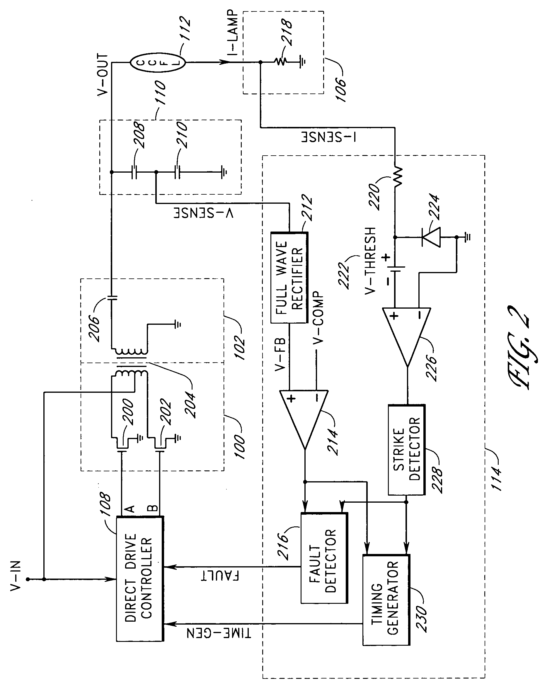
[0023] Embodiments of the present invention will be described hereinafter with reference to the drawings. FIG. 1 is a block diagram of a power conversion circuit according to one embodiment of the present invention. The power conversion circuit (or the lamp inverter) converts a substantially DC input voltage (V-IN) into a substantially AC output voltage (V-OUT) to drive a CCFL 112. An AC current (or a lamp current) flows through the CCFL 112 to provide illumination in an electronic device 104, such as, for example, a flat panel display, a personal digital assistant, a palm top computer, a scanner, a facsimile machine, a copier, or the like.

[0024] The power conversion circuit includes a PWM controller 108, a primary network 100, a secondary network 102, a current feedback circuit 106, a voltage feedback circuit 110 and a strike circuit 114. The input voltage (or the supply voltage) is provided to the primary network 100 and the PWM controller 108. The primary network 100 is controll...


PUM

PropertyMeasurementUnit
voltageaaaaaaaaaa
frequencyaaaaaaaaaa
currentaaaaaaaaaa

Abstract

A lamp inverter with continuous strike voltage facilitates faster striking of a fluorescent lamp, especially at cold temperatures. A frequency sweep generator sweeps the frequency of the lamp inverter to a striking frequency corresponding to a striking lamp voltage and then maintains the striking frequency until the lamp strikes.

Description

RELATED APPLICATIONS [0001] This application is a continuation of and claims benefit of priority under 35 U.S.C. § 120 from U.S. patent application Ser. No. 10 / 453,760, filed on Jun. 3, 2003, which claims the benefit of priority under 35 U.S.C. § 119(e) of U.S. Provisional Application No. 60 / 433,557 entitled “Apparatus and Method for Striking a Fluorescent Lamp,” filed on Dec. 13, 2002, the entirety of each of which is hereby incorporated herein by reference.BACKGROUND OF THE INVENTION [0002] 1. Field of the Invention [0003] The present invention relates to a power conversion circuit for driving fluorescent lamps, such as, for example, cold cathode fluorescent lamps (CCFLs), and more particularly relates to starting a fluorescent lamp with improved efficiency. [0004] 2. Description of the Related Art [0005] Fluorescent lamps are used in a number of applications where light is required but the power required to generate the light is limited. One particular type of fluorescent lamp is...

Claims


Application Information

Patent Timeline
Patent Type & Authority Applications(United States)
IPC IPC(8): H05B37/02H05B41/282H05B41/285H05B41/38H05B41/392
CPCH05B41/2822H05B41/2824H05B41/3927H05B41/382H05B41/2855Y10S315/07
Inventor HENRY, GEORGE C.
Owner MICROSEMI CORP
Learn More