
Circuit health monitoring system and method

Active Publication Date: 2006-02-23
HAMILTON SUNDSTRAND CORP
View PDF9 Cites 180 Cited by
  • Summary
  • Abstract
  • Description
  • Claims
  • Application Information

AI Technical Summary

Benefits of technology

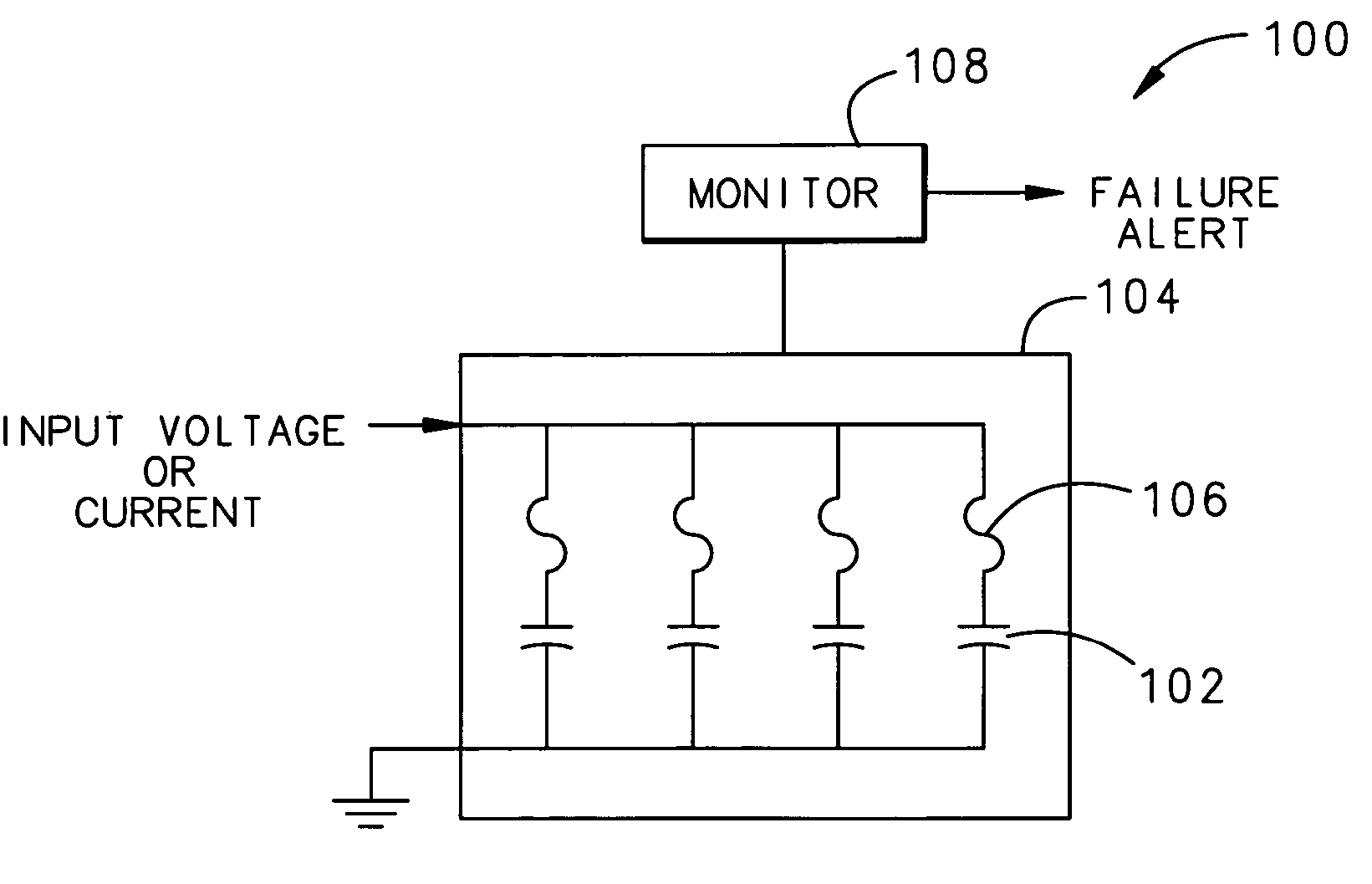
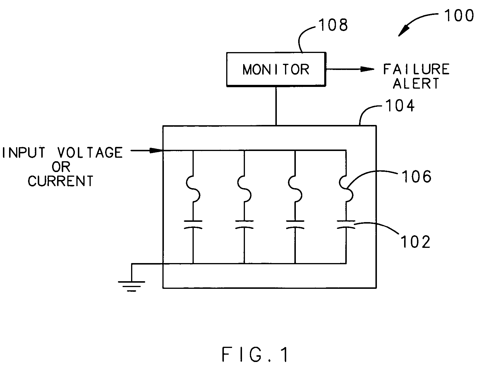
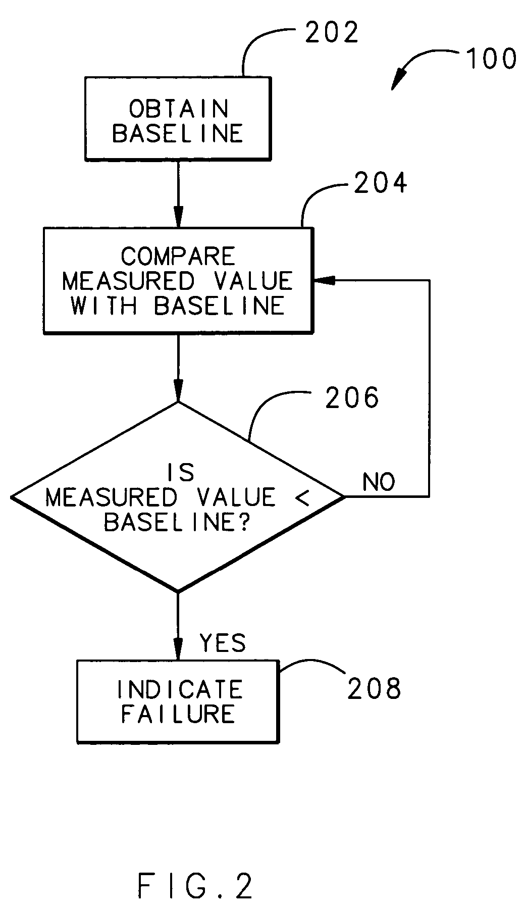
[0007] After the module is installed in the system, the monitor compares the capacitance of the module with the baseline obtained during operating or test conditions. If any of the capacitors in the module fails in an open state or a shorted state, the actual capacitance of the module will be different than the baseline. However, the redundant capacitive elements allow the system to continue operating with one, or even more than one, failed capacitive element. Thus, the monitor can notify the user about the failed capacitive element without requiring the user to replace the failed capacitive element immediately. The user can therefore replace the failed capacitive element as part of scheduled maintenance, reducing maintenance and operating costs caused by unexpected, unscheduled maintenance.

Problems solved by technology

Although COTS hardware tends to be less expensive and more readily available than custom-made parts, COTS hardware also tends to have reduced lifespan and reliability.
Thus, COTS hardware including capacitors, such as those used in inverter / converter applications, may experience occasional failures as they age.
When a capacitor fails, it can fail in either a shorted state or an open state.
If the capacitor fails in a shorted state, current is allowed to flow freely through the system, potentially causing functional failure of electronic devices in the system.
If the capacitor fails in an open state, it degrades or eliminates the protection offered by the capacitor and can cause other functional failures as well.
Capacitor failures tend to be hard-failures; that is, they can occur without warning and cause the system to be inoperable until the capacitor is replaced.
For example, if the capacitor stores energy used to start an engine, failure of that capacitor will make the engine unable to start.
Other problems discovered only after the capacitor failure renders a system inoperable results in unplanned delays as the failed capacitor is replaced on an ad hoc basis.

Method used


Image

  • Circuit health monitoring system and method
  • Circuit health monitoring system and method
  • Circuit health monitoring system and method

Examples


Embodiment Construction

[0011]FIG. 1 illustrates a system 100 that provides fail-soft, fail-safe operation of capacitive elements 102 in the system 100. Rather than including only the minimum number of capacitors to provide system functionality (e.g., filtering, wave shaping, EMI / HIRF / lightning protection, etc.), the system 100 includes a module 104 having redundant capacitive elements or capacitive elements 102. The capacitive elements 102 in the module 104 are arranged in parallel. Note that multiple capacitive elements 102 may exist within a single capacitor; thus, the term “capacitive elements” in this description will broadly cover both individual capacitive elements as well as capacitors containing multiple capacitive elements. Using redundant capacitive elements 102 ensures that there will be sufficient capacitance to maintain at least a minimum level of system functionality even when one or more of the individual capacitive elements 102 fail.

[0012] The capacitive elements 102 in the module 104 may...


PUM


Abstract

A system and method that provides early warning of a capacitor failure before it causes a functional failure by including a plurality of redundant capacitive elements arranged in parallel in a capacitor module. A monitor measures a value corresponding to the total capacitance of the module under a selected system operating condition to obtain a baseline value. During system operation, the monitor compares a measured value with the baseline. If any of the capacitive elements in the module fails in an open state or a shorted state, the measured value will differ respect to the baseline, but the remaining capacitive elements allow the system to continue to operate. The user can therefore replace the failed capacitor as part of scheduled maintenance, reducing maintenance and operating costs caused by unexpected, unscheduled maintenance.

Description

TECHNICAL FIELD [0001] The present invention relates to circuit health monitoring systems and methods that detect potential failures in circuit components. BACKGROUND OF THE INVENTION [0002] DC or AC electric power distribution systems using local voltage and current conversion circuits are increasingly being used in aerospace, military, industrial, transportation, and other industries. In these environments, solid state inverter circuits are used to locally convert voltage and current to required levels at application sites (e.g., an airframe). These inverter circuits commonly use capacitors for waveform shaping, for protection against electromagnetic interference (EMI), high-intensity radiated fields (HIRF) and lightning, and for other functional and protective functions. Capacitors may be included in both motor control units and inverter / converter units in the system, for example. [0003] Many industries are increasing the use of commercial off-the-shelf (COTS) hardware to meet co...

Claims


Application Information

Patent Timeline
IPC IPC(8): G08B21/00G01R31/08
CPCG01R31/40G01R31/343
Inventor SCHNETKER, TED R.
Owner HAMILTON SUNDSTRAND CORP
Learn More