System and method for implementing a multi-monitor interface for a data processing system

a data processing system and multi-monitor technology, applied in the field of data processing system interfaces, can solve the problems of not being able to identify the move-allowing section b-c, user may move the mouse pointer mp unintentionally onto the other screen, and achieve the effect of enhancing the operability of the pointing devi

Inactive Publication Date: 2006-02-23
IBM CORP
View PDF3 Cites 25 Cited by
  • Summary
  • Abstract
  • Description
  • Claims
  • Application Information

AI Technical Summary

Benefits of technology

[0018] An object of the present invention is to provide a multi-monitor system, a multi-monitor method, and a mark displaying program product for an extended desktop environment where screens of two or more monitors are virtually connected and a pointer displayed in compliance with a pointing device is bi-directionally movable between screens, which are capable of enhancing operability of a pointing device.
[0022] In this system, the object for identifying the predetermined position is displayed at least on one screen of the first and second monitors. Accordingly, it is possible to identify the position where the pointer is bi-directionally movable between the screens. As a result, it is easy to move the pointer bi-directionally between the both screens without losing sight of the pointer, for example. In this way, it is possible to enhance operability of the pointing device.
[0025] Preferably, the multi-monitor system further includes means for stopping display of the mark window which is activated when the pointer is moved onto the mark window or in the vicinity thereof.
[0026] In this case, the mark window is concealed when the pointer is moved onto the mark window or in the vicinity thereof. Accordingly, it is also possible to operate an object (such as an icon, a task bar, a tool bar, or another window) hidden behind the mark window. In this way, the mark window does not bother other operations.
[0034] In this case, when the pointer reaches the section on the edge other than the predetermined section, the pointer is allowed to skip to one of the both ends of the predetermined section closer to the position of the pointer, and is moved to the other screen. Accordingly, it is possible to move the pointer in the section other than the predetermined section. Moreover, the pointer is forcibly stopped when the pointer reaches the section other than the predetermined section, and the pointer is moved to the other screen when the user further tries to move the pointer from one of the screens to the outside. In this way, the user will not move the pointer to the other screen unintentionally.
[0040] According to this program product, the object for identifying the predetermined position is displayed at least on one screen of the first and second monitors. Accordingly, it is possible to identify the position where the pointer is bi-directionally movable between the both screens. As a result, it is easy to move the pointer bi-directionally between the both screens without losing sight of the pointer, for example. In this way, it is possible to enhance operability of the pointing device.

Problems solved by technology

However, when moving the mouse pointer MP on the screen M1 of the primary monitor in the right direction toward a section C-D, the mouse pointer MP is stopped on the section C-D and it is not possible to move the mouse pointer MP onto the screen M2 of the secondary monitor.
As a result, the following problems arise.
However, in reality, the physical positional relation between the both screens M1 and M2 does not always coincide with the virtual positional relation, hence it is not possible to identify the move-allowing section B-C.
Second, when the user operates the mouse pointer MP in the vicinity of the move-allowing section B-C of the mouse pointer MP, the user may move the mouse pointer MP unintentionally onto the other screen.
However, when the move-allowing section of the mouse pointer MP is limited, the mouse pointer MP once moved does not come back to the original screen soon, and it may take quite a long time to discover the mouse pointer MP.

Method used


Image

  • System and method for implementing a multi-monitor interface for a data processing system
  • System and method for implementing a multi-monitor interface for a data processing system
  • System and method for implementing a multi-monitor interface for a data processing system

Examples


Embodiment Construction

[0078] Now, an embodiment of the present invention will be described in detail with reference to the accompanying drawings. In the drawings, identical or similar constituents are designated by identical reference numerals, and repetitive explanation will be omitted.

1. Configuration

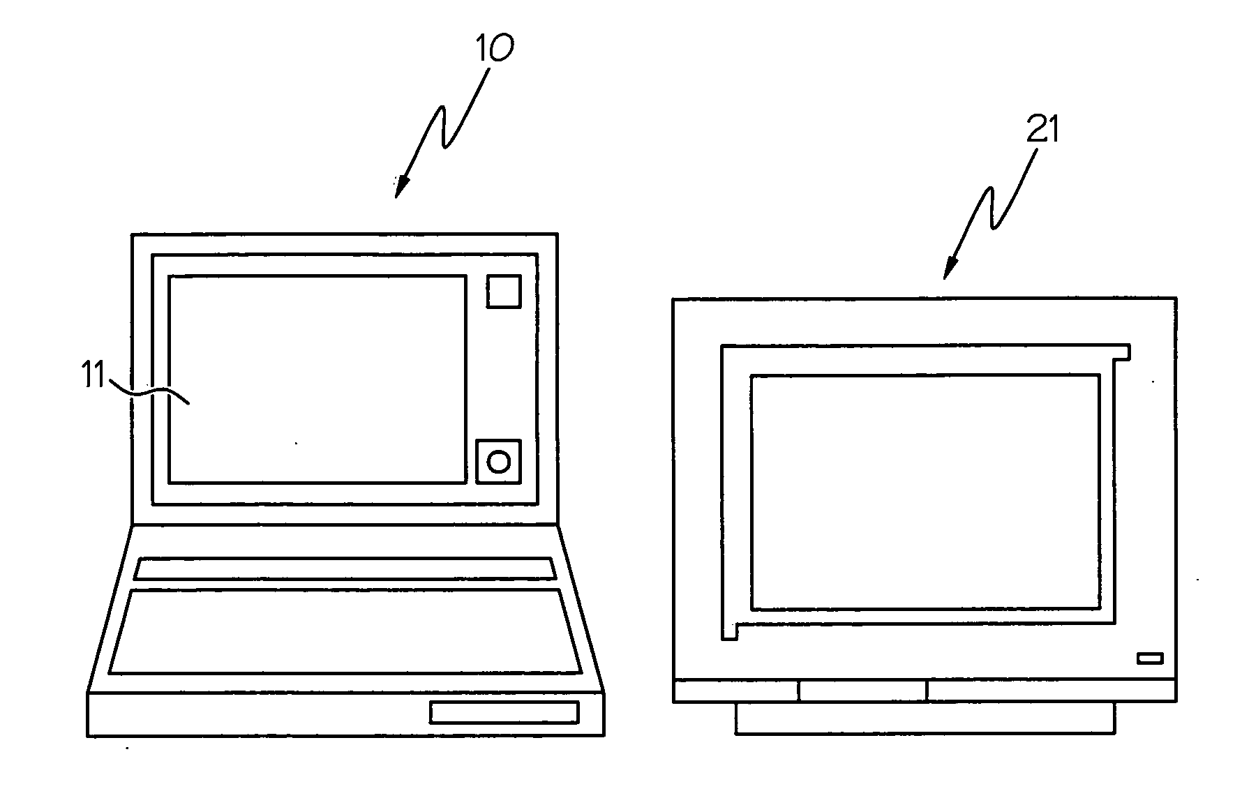
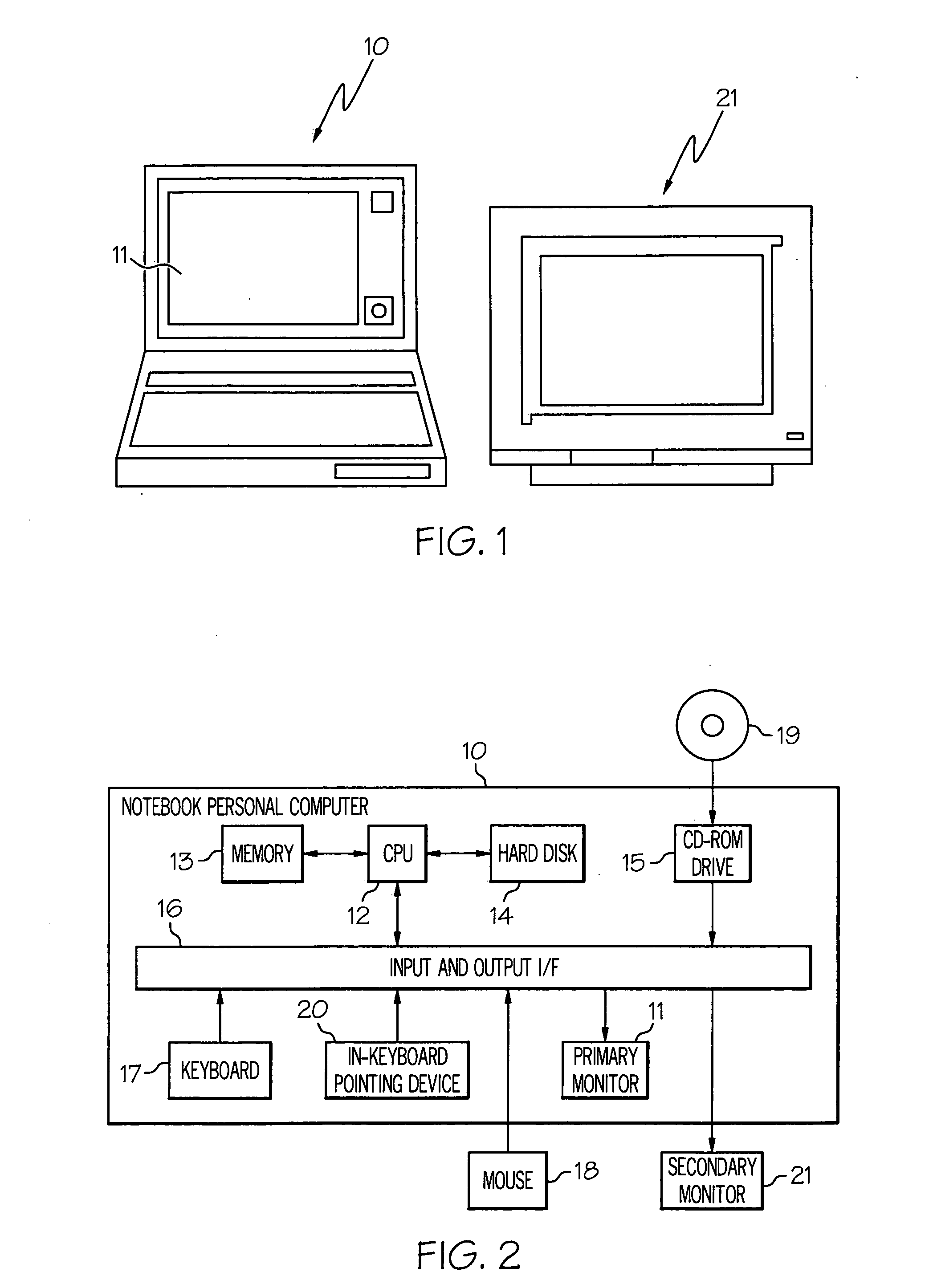
[0079] Referring to FIG. 1, a multi-monitor system 1 according to an embodiment of the present invention includes a notebook personal computer 10 and an external monitor 21. In this embodiment, a monitor 11 of the notebook personal computer 10 functions as a primary monitor and the external monitor 21 functions as a secondary monitor.

[0080] Referring to FIG. 2, the notebook personal computer 10 includes a central processing unit (CPU) 12, a memory 13, a hard disk 14, a compact disk-read only memory (CD-ROM) drive 15, and an input and output interface 16. A keyboard 17, an in-keyboard pointing device 20, and the primary monitor 11 are connected to the input and output interface 16. In addition, a mouse ...


PUM


Abstract

To provide a multi-monitor system capable of enhancing operability of a mouse in an extended desktop environment. When a screen M1 of a primary monitor 11 is connected to a screen M2 of a secondary monitor 21 in a shifted manner at a predetermined section B2-D1, mark windows 50 are displayed on the screen M1 of the primary monitor 11 and the screen M2 of the secondary monitor 21 adjacently to the predetermined section B2-D1 in order to accurately and promptly grasp the predetermined position B2-D1 where a mouse pointer MP is movable. As options, the mark window 50 is hidden when the mouse pointer MP is moved onto the mark window 50 or in the vicinity thereof, the mouse pointer MP is temporarily stopped at the predetermined section, and a number of a destination monitor is displayed on the original screen when the mouse pointer MP is moved to the other screen.

Description

PRIORITY CLAIM [0001] This application claims priority of Japanese Patent Application No. JP2004-242381, filed on Aug. 23, 2004, and entitled, “Multi-Monitor System, Multi-Monitor Method and Mark Displaying Program Product.”BACKGROUND OF THE INVENTION [0002] 1. Technical Field [0003] The present invention relates in general to the field of data processing systems. More particularly, the present invention relates to the field of data processing system interfaces. Still more particularly, the present invention relates to a system and method of implementing a multi-monitor interface for a data processing system. [0004] 2. Description of the Prior Art [0005] The present invention relates to a multi-monitor system, a multi-monitor method, and a mark displaying program product. More specifically, the present invention relates to a multi-monitor system, a multi-monitor method, and a mark displaying program product to be operated in an extended desktop environment in which screens of two or...

Claims


Application Information

Patent Timeline
Patent Type & Authority Applications(United States)
IPC IPC(8): G09G5/00G06F3/048G06F3/0481G06F3/0489
CPCG06F3/0481G09G5/08G06F3/1423
Inventor MORI, HIDETOSHIKONDO, TOMOAKI
Owner IBM CORP
Why Eureka
Try Eureka