
Balloon illuminator

a technology of illuminating devices and balloons, which is applied in the direction of semiconductor devices for light sources, toy aircraft, light and heating apparatus, etc., can solve the problems of shortening the effective life of balloons, affecting the effect of light and sound, and damage to balloons

Inactive Publication Date: 2006-02-23
OXBORROW DOUGLAS GRANT
View PDF13 Cites 21 Cited by
  • Summary
  • Abstract
  • Description
  • Claims
  • Application Information

AI Technical Summary

Benefits of technology

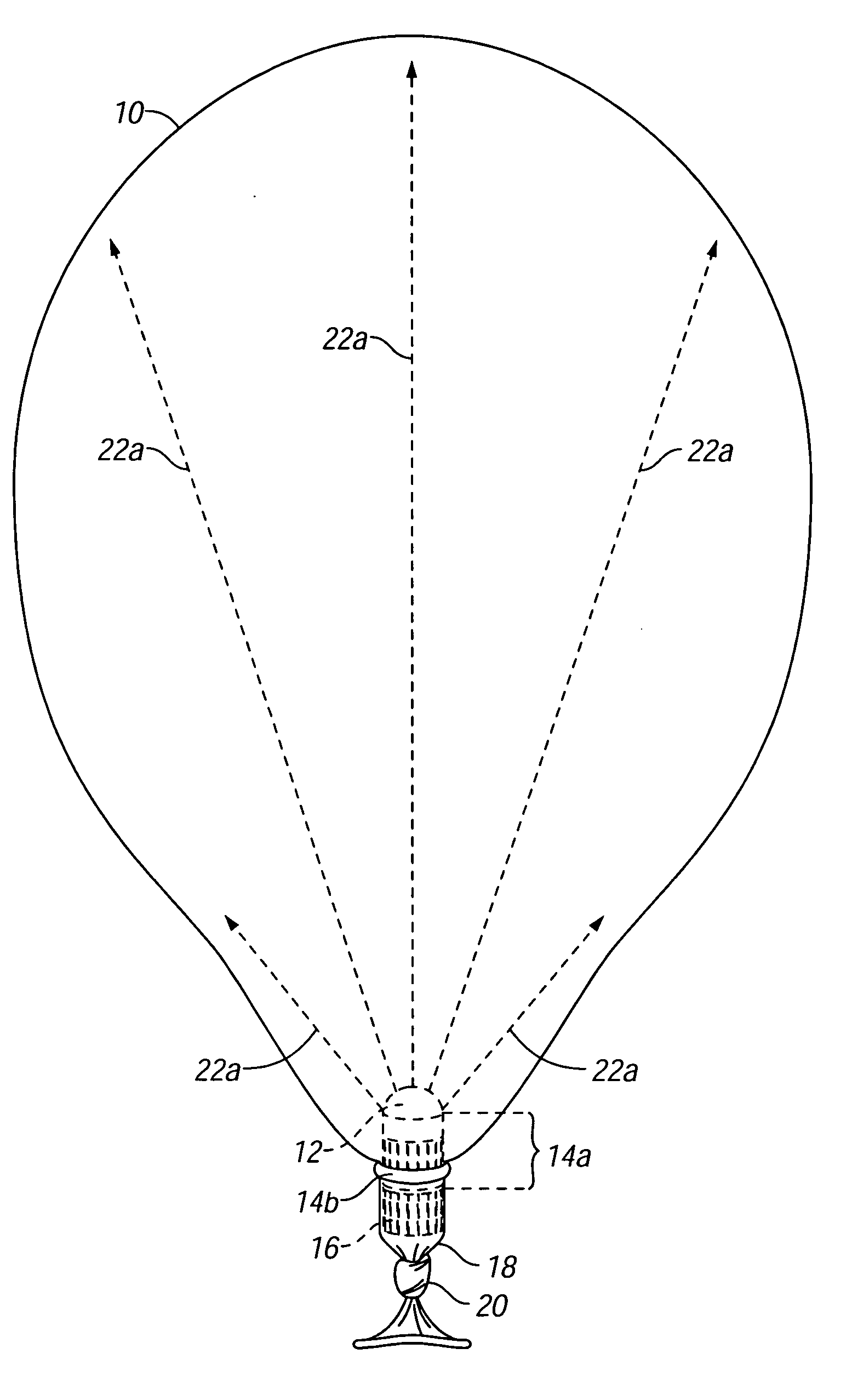
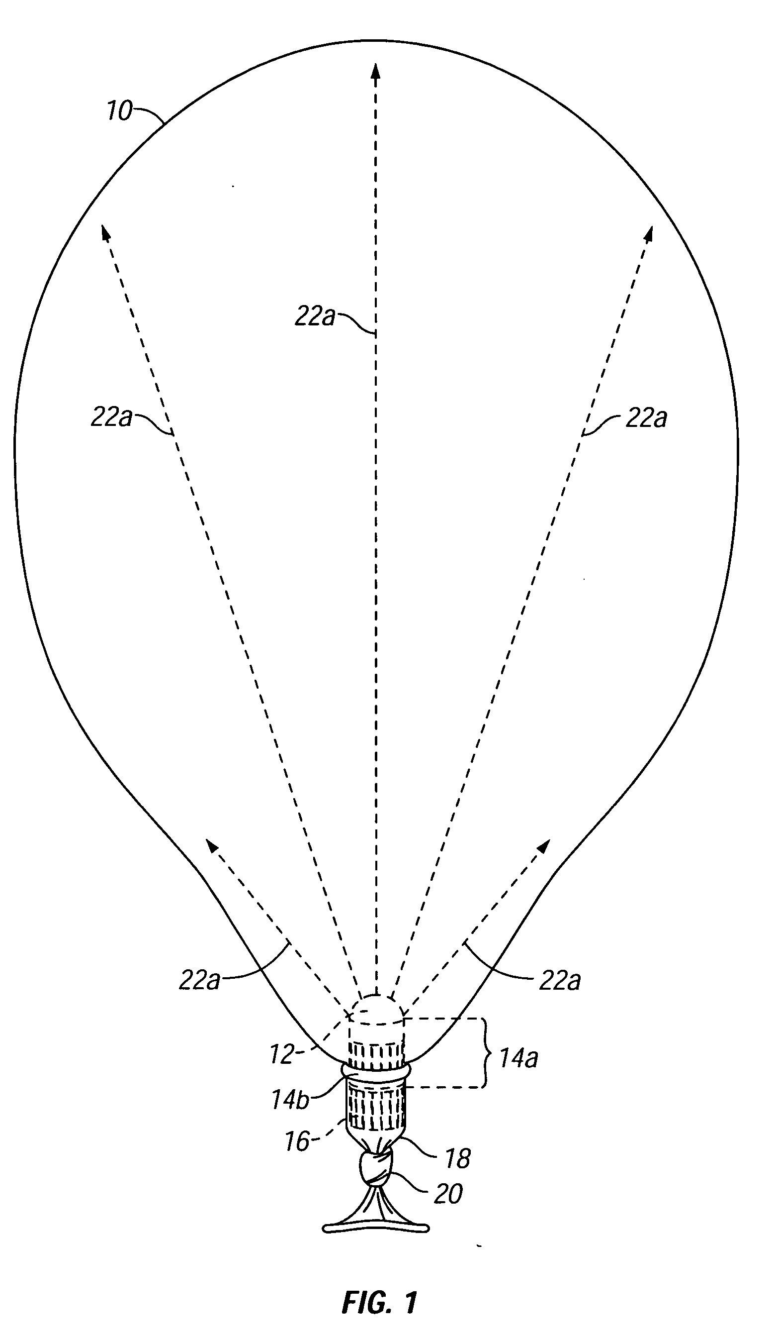
[0010] The subject invention relates to a novel device for use in illuminating the interior of a balloon. More particularly, this novel balloon illuminator includes a light emitting diode (or L.E.D.), which does not emit heat, a direct current power source (such as one or more batteries), means to switch the light emitted from a constant light to a flashing light, all contained in a housing sized to fit easily within the neck of a party balloon, with the inner lining of said housing made of electricity conducting material so that when fully assembled th

Problems solved by technology

Latex balloons might be damaged by the heat generated by such a light source.
A heat emitting light source facilitates the escape of gas from a lighter than air balloon, thus cutting short its effective life.
Balloon illumination devices that attach a heat generating light source to the outer surface of a balloon, such as Perez (U.S. Pat. No. 5,117,344), suffer from the same disadvantages.
The inability to carry balloons outdoors or freely indoors, of course, severely restricts their utility.
Though they may differ, such means for creating apertures imply a relatively complex method for illuminating the balloon and a cumbersome and not self-contained apparatus, with the light source, power source and means for creating a sufficient sized aperture in the neck of the balloon separated.

Method used


Image

  • Balloon illuminator
  • Balloon illuminator
  • Balloon illuminator

Examples


Embodiment Construction

[0025] A preferred embodiment of the balloon illuminator is a L.E.D. or light emitting diode included in an electrical circuit that causes the L.E.D. to flash when the battery, i.e. direct current power source, is oriented one way and that causes the L.E.D. to emit a constant light when the polarity of the direct current power source is reversed. All of the components of the balloon illuminator are included in a single housing that is sized to fit easily into or through the neck of a party balloon where the balloon illuminator may be affixed by an O-ring or other ligature means. The weight and size of the balloon illuminator are such that a standard ten inch party balloon with a balloon illuminator affixed may remain afloat if filled with lighter than air gas.

[0026] In its preferred embodiment, a balloon illuminator includes, as shown in FIG. 2, a lens 12, a light emitting diode 13a, an integrated circuit forming the base of the light emitting diode 13b, the top half of a housing 1...


PUM


Abstract

A balloon illuminator that can emit either a flashing or constant light depending on the polarity of the battery used to power the device. The device can be modified to cycle through a series of colors. The balloon illuminator is comprised of a lens, light emitting diode, a battery, and means to switch the balloon illuminator from flashing to constant light mode depending on the polarity of the battery and a housing lined with electricity conducting material. Once fully assembled, with each component contained in the housing, the electrical circuit formed by housing and components is closed and the balloon illuminator emits light. The balloon illuminator also works without a lens, though in the preferred embodiment, the lens is used to disperse the light more fully in the interior of the balloon. A balloon illuminator that uses a multi color light emitting diode can cycle through a series of colors once the illuminator is fully assembled and the electrical circuit completed. The balloon illuminator is impervious to liquid and is compatible with liquid sealants used to coat the inner lining of latex balloons to prevent leakage of gas.

Description

REFERENCE TO RELATED PROVISIONAL APPLICATIONS [0001] This application claims the benefit of the filing date of U.S. provisional patent application Ser. No. 60 / 603,649, filed Aug. 23, 2004, by Douglas Grant Oxborrow and entitled BALLOOMINATOR BALLOON LIGHT.BACKGROUND [0002] 1. Field of the Invention [0003] This invention relates to a balloon illuminating device, i.e. a balloon illuminator, that is compatible with balloons and specifically lighter than air balloons. [0004] 2. Background of the Invention [0005] Previous balloon illumination devices differ from and are inferior to the subject invention in several respects. [0006] Some such efforts place a heat emitting light source, such as a light bulb, inside inflated latex balloons to provide illumination. Examples of such efforts include Akman (U.S. Pat. No. 5,119,281), Neumeier (U.S. Pat. No. 4,794,498) and Marletta (U.S. Pat. No. 4,452,445). Latex balloons might be damaged by the heat generated by such a light source. A heat emitt...

Claims


Application Information

Patent Timeline
IPC IPC(8): F21L4/00
CPCA63H27/10A63H2027/1058F21Y2101/02F21V5/048F21V3/023F21Y2115/10
Inventor OXBORROW, DOUGLAS GRANT
Owner OXBORROW DOUGLAS GRANT
Learn More