
Diode-pumped laser

a laser and diode technology, applied in the direction of laser details, optical resonator shape and construction, excitation process/apparatus, etc., can solve the problems of compromising pumping efficiency, complicated manufacturing process, and difficulty in adopting diode lasers for specific applications

Active Publication Date: 2006-02-23
LUMENTUM OPERATIONS LLC
View PDF12 Cites 17 Cited by
  • Summary
  • Abstract
  • Description
  • Claims
  • Application Information

AI Technical Summary

Benefits of technology

[0018] In accordance with another aspect of the invention, the first end of the gain element is located at a distance of at least 0.001″ from the output facet of the laser diode, said distance sele...

Problems solved by technology

However there are difficulties associated with adopting diode lasers for specific applications.
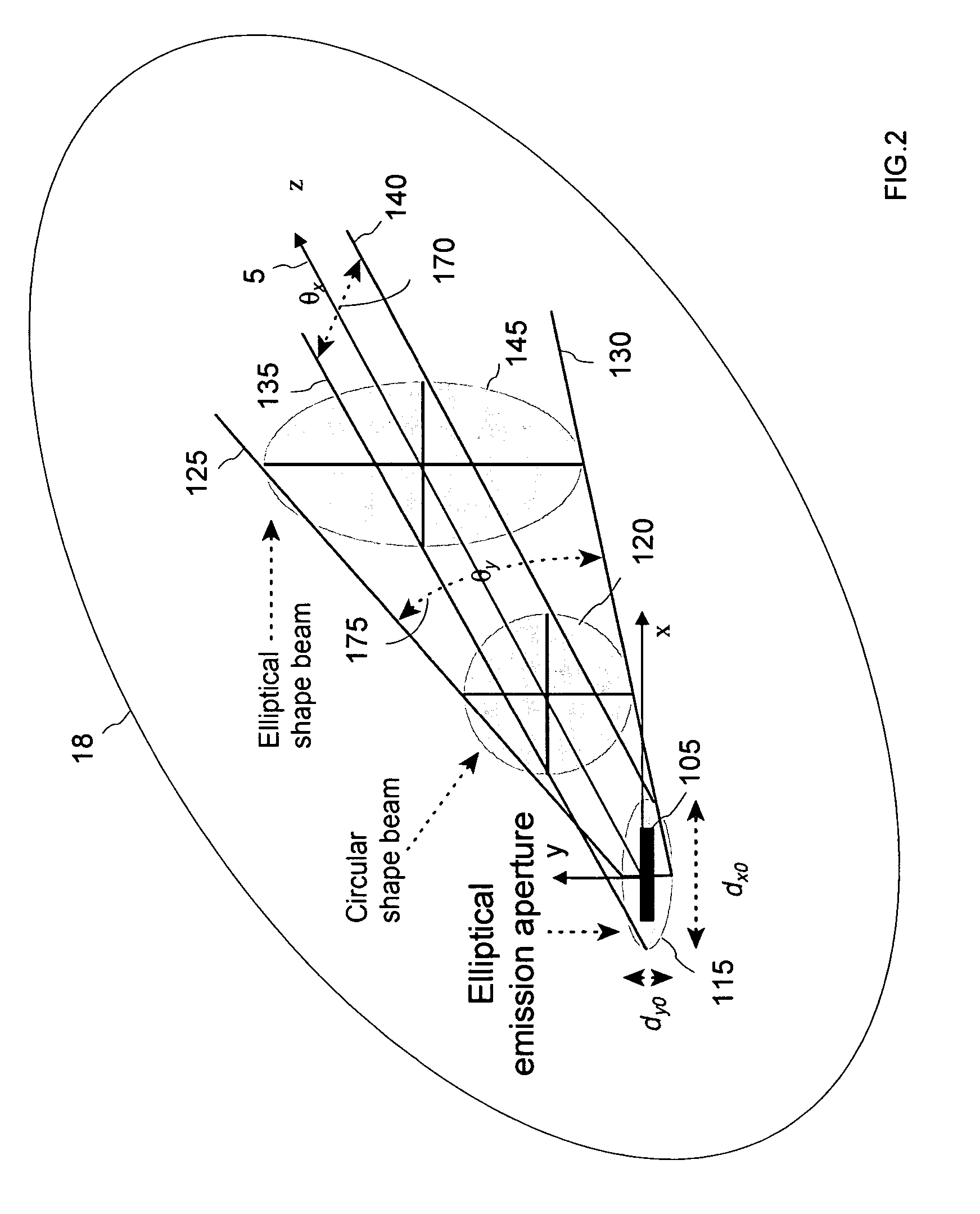
The ellipticity and astigmatism of the pump beam can compromise pumping efficiency, especially in applications where a circular-symmetric output laser beam with an approximately Gaussian intensity profile is of importance.
Although using such coupling optics does allow better matching of the pumped volume with the fundamental laser mode, it requires additional alignment steps which complicate the manufacturing process and increase laser cost.
However, the output laser efficiency may suffer in such a configuration due to the elliptical crossection of the pumped region in the gain material, which does not match well with a fundamental laser mode having circular symmetry.
The butt-coupled pumping arrangement may also limit the emitting aperture range and the aspect ratio of the pump laser diodes that can be used for single-mode operation of the diode-pumped laser; high-power laser diodes having wide and thin emitting aperture butt-coupled to a laser crystal may excite a sufficiently wide mode-volume to cause higher-order spatial modes to appear in the laser output, or to lead to a non-circular laser output beam.
Another drawback of the butt-coupled pumping arrangement is an associated requirement to bring the pump diode laser and the laser crystal in a very close proximity during the laser assembly, with an associated risk of damaging the laser diode's output facet and reducing yield of good lasers in manufacturing.

Method used


Image

  • Diode-pumped laser
  • Diode-pumped laser
  • Diode-pumped laser

Examples


Embodiment Construction

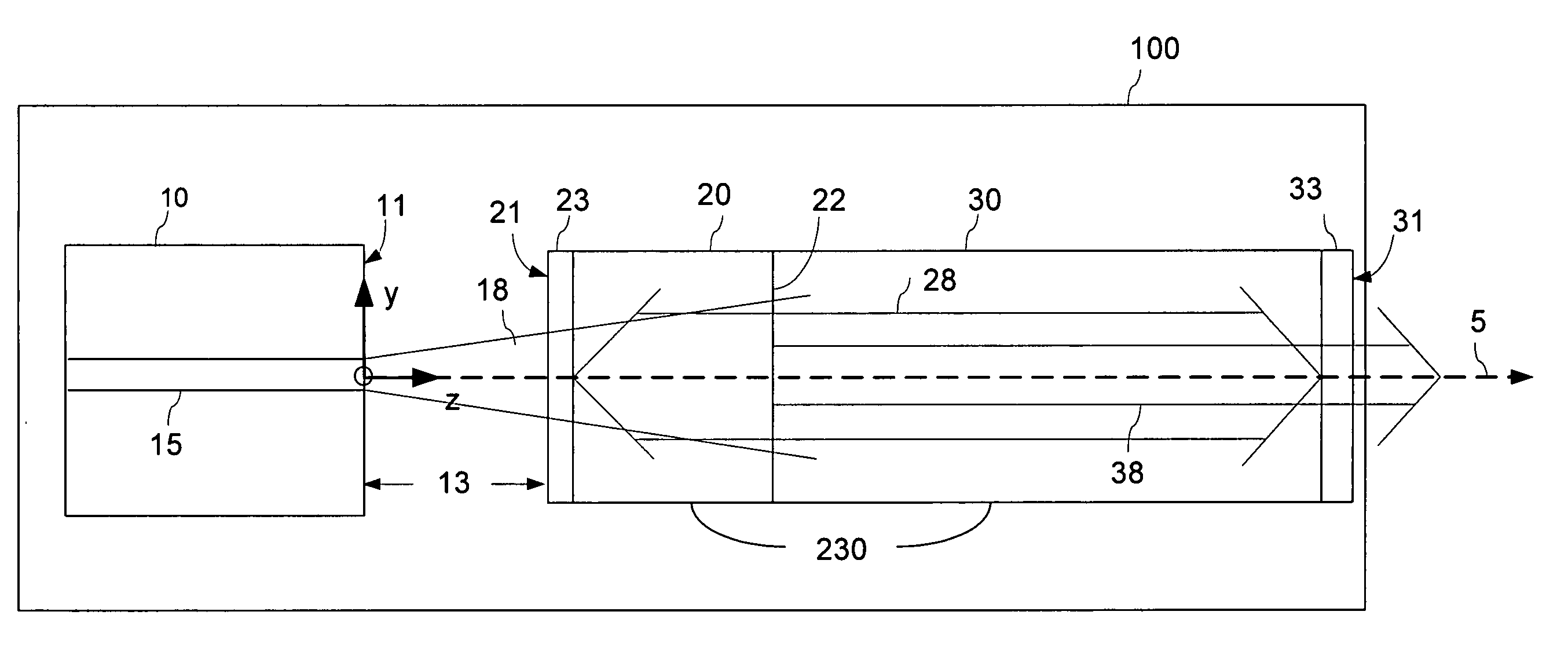
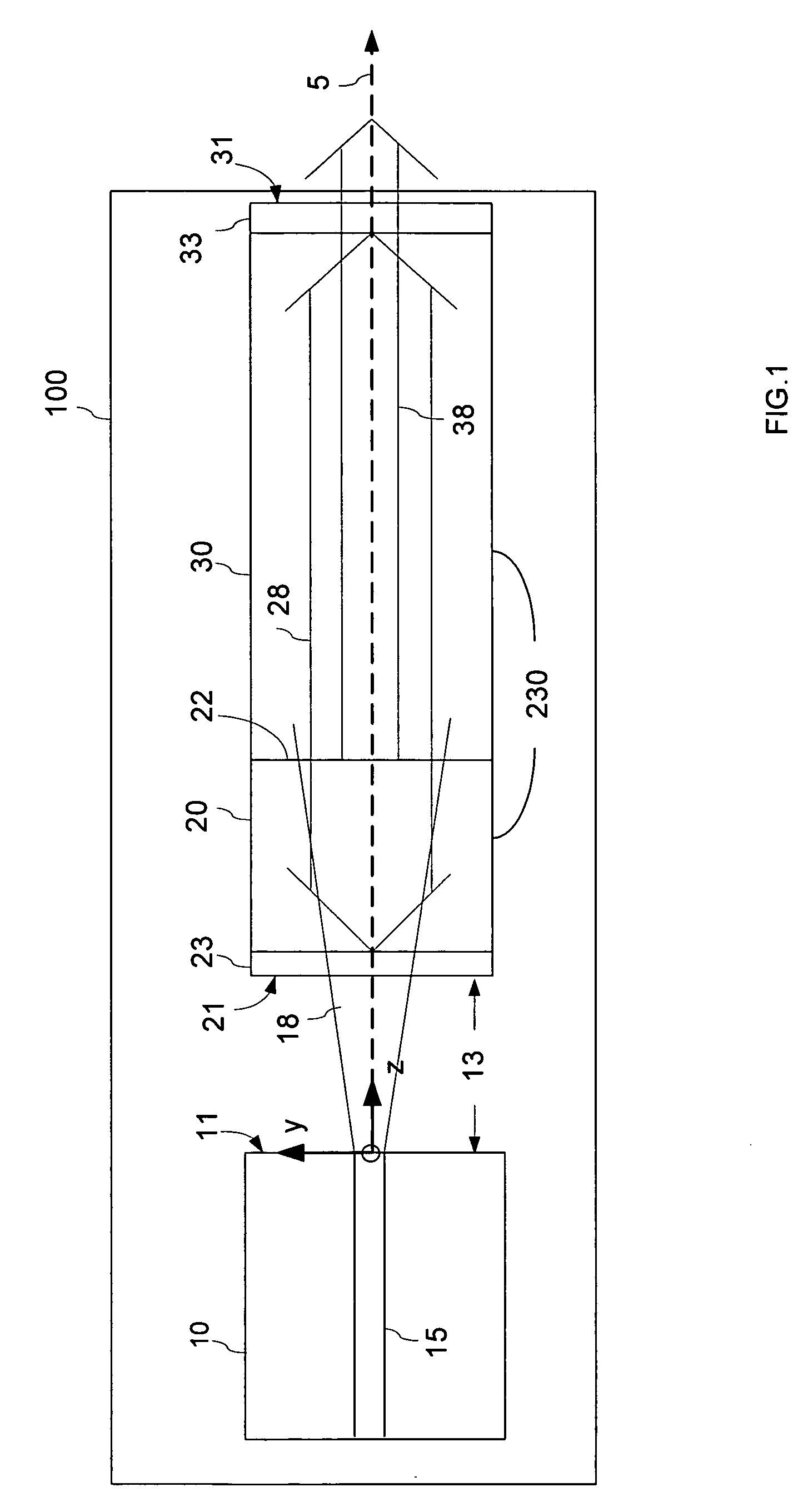
[0027] The invention is a direct-coupled diode-pumped laser employing a high-power laser diode pump emitting an astigmatic and divergent pump beam with an elliptical cross-section at the laser diode pump output, wherein a laser crystal is disposed at a substantial distance from the laser diode pump exceeding 0.001″, in a location where the pump beam has a substantially circular cross-section in the absence of coupling lens elements therebetween. The astigmatic pump beam is therefore directly coupled into the laser crystal without prior beam re-shaping, providing a pump beam in the laser crystal, which is spatially matched to a fundamental laser mode for obtaining an optimum laser efficiency and a circular-symmetric output laser beam.

DESCRIPTION OF THE PREFERRED EMBODIMENT

[0028] An exemplary embodiment of a direct-coupled diode-pumped laser of present invention is shown in FIG. 1 and is hereafter described.

[0029] A gain element 20 having a first end 21 and a second end 22 is dispo...


PUM


Abstract

A diode-pumped laser with a direct edge coupling of a pump beam is provided. The laser includes a microchip laser cavity optically pumped by a laser diode emitting an astigmatic pump beam having a substantially elliptical beam cross-section at an output laser diode facet. The microchip laser cavity is disposed at a substantial distance exceeding 0.001″ from the laser diode pump where the astigmatic pump beam has a greatly reduced ellipticity, providing high laser output efficiency without coupling lens element between the laser cavity and the laser diode pump. The pumping arrangement is favourable for single-mode lasing. In some embodiments, the laser cavity includes nonlinear crystal for intra-cavity SHG, a saturable absorber for passive Q-switching and mode locking, and a polarizing prism.

Description

[0001] This application claims priority from U.S. Provisional Patent Application No. 60 / 603,802 filed Aug. 23, 2004, entitled “Diode-Pumped Microchip Laser With Butt-Coupled Pump Source Single Frequency / Low Noise Monolithic Microchip Laser With Intracavity Polarizer”, which is incorporated herein by reference for all purposes.FIELD OF THE INVENTION [0002] The present invention generally relates to diode-pumped solid-state lasers, and more particularly to end-pumped microchip solid-state lasers wherein diode pumping is affected in the absence of intermediate pump beam focusing or collimating elements. BACKGROUND OF THE INVENTION [0003] Diode lasers have been widely used as pump sources in solid-state laser applications. They are efficient, compact, and available at several red and near-IR wavelengths. However there are difficulties associated with adopting diode lasers for specific applications. In particular, most high-power commercial pump diodes are of the edge-emitting type, and ...

Claims


Application Information

Patent Timeline
IPC IPC(8): H01S3/09
CPCH01S3/0604H01S3/0612H01S3/0627H01S3/08H01S3/113H01S3/08054H01S3/09415H01S3/109H01S3/08036
Inventor LEI, GANGHULSE, CHARLES ANDYISSIER, VINCENTBRADLEY,, RICHARD A. JR.WAARTS, ROBERT G.
Owner LUMENTUM OPERATIONS LLC
Learn More