C-arm device with adjustable detector offset for cone beam imaging involving partial circle scan trajectories

Inactive Publication Date: 2006-02-23
SIEMENS MEDICAL SOLUTIONS USA INC
View PDF6 Cites 52 Cited by
  • Summary
  • Abstract
  • Description
  • Claims
  • Application Information

AI Technical Summary

Benefits of technology

[0007] By way of introduction, the embodiments described below include methods, processes, apparatuses, instructions, or systems for reconstructing enhanced volumes using C-arm x-ray imaging systems. Two partial circular scans may be performed by a C-arm imaging system. The C-arm may comprise an x-ray detector having a movable stage. The movable stag

Problems solved by technology

Given the size of the detector and the object to be imaged, it is common for this not to be feasible unless the patient is moved and multiple projections are taken such that they can be stitched together for a full view.
Unfortunately, this approach is not very practical, because it can only applied for selec

Method used


Image

  • C-arm device with adjustable detector offset for cone beam imaging involving partial circle scan trajectories
  • C-arm device with adjustable detector offset for cone beam imaging involving partial circle scan trajectories
  • C-arm device with adjustable detector offset for cone beam imaging involving partial circle scan trajectories

Examples


Embodiment Construction

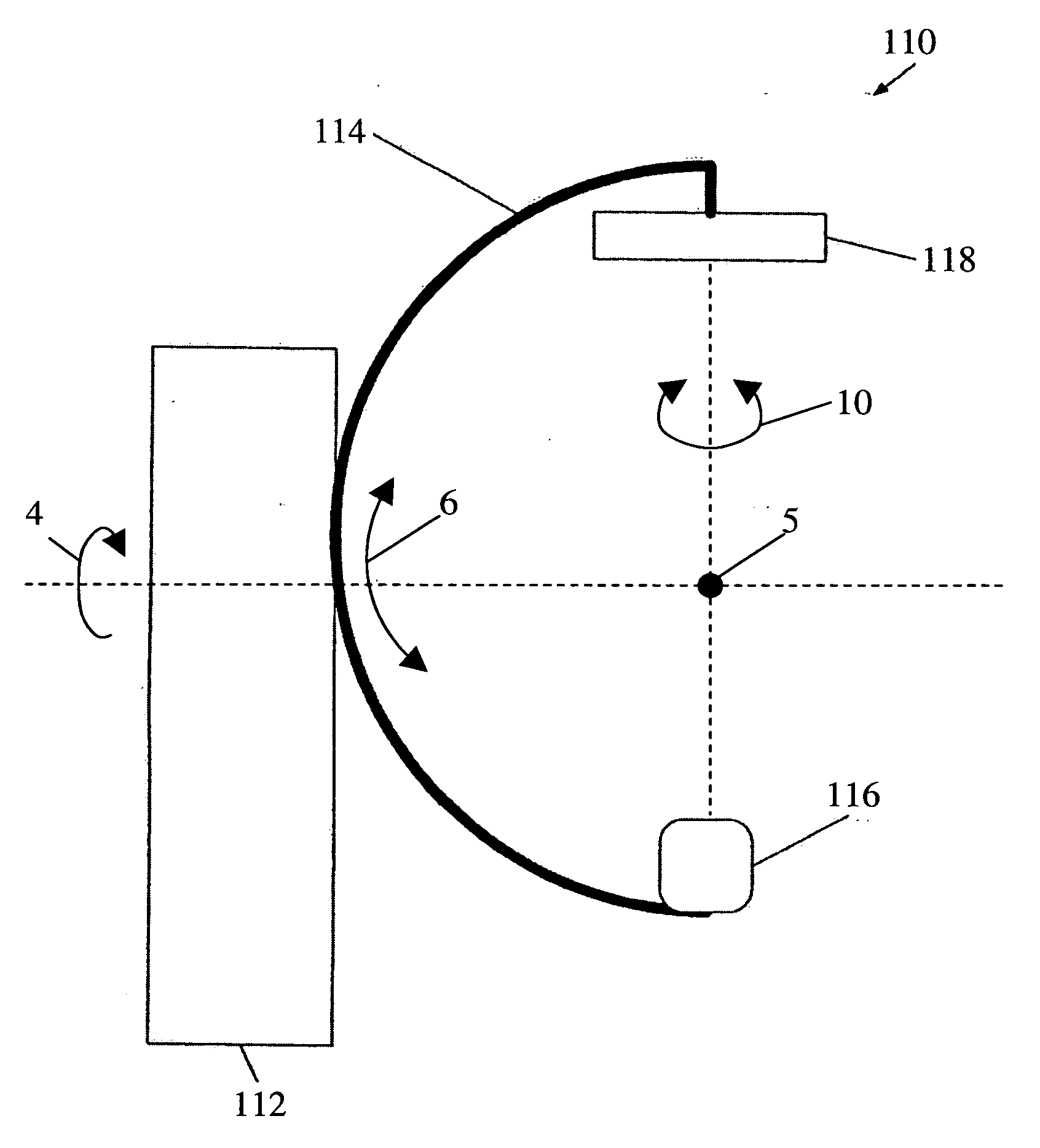
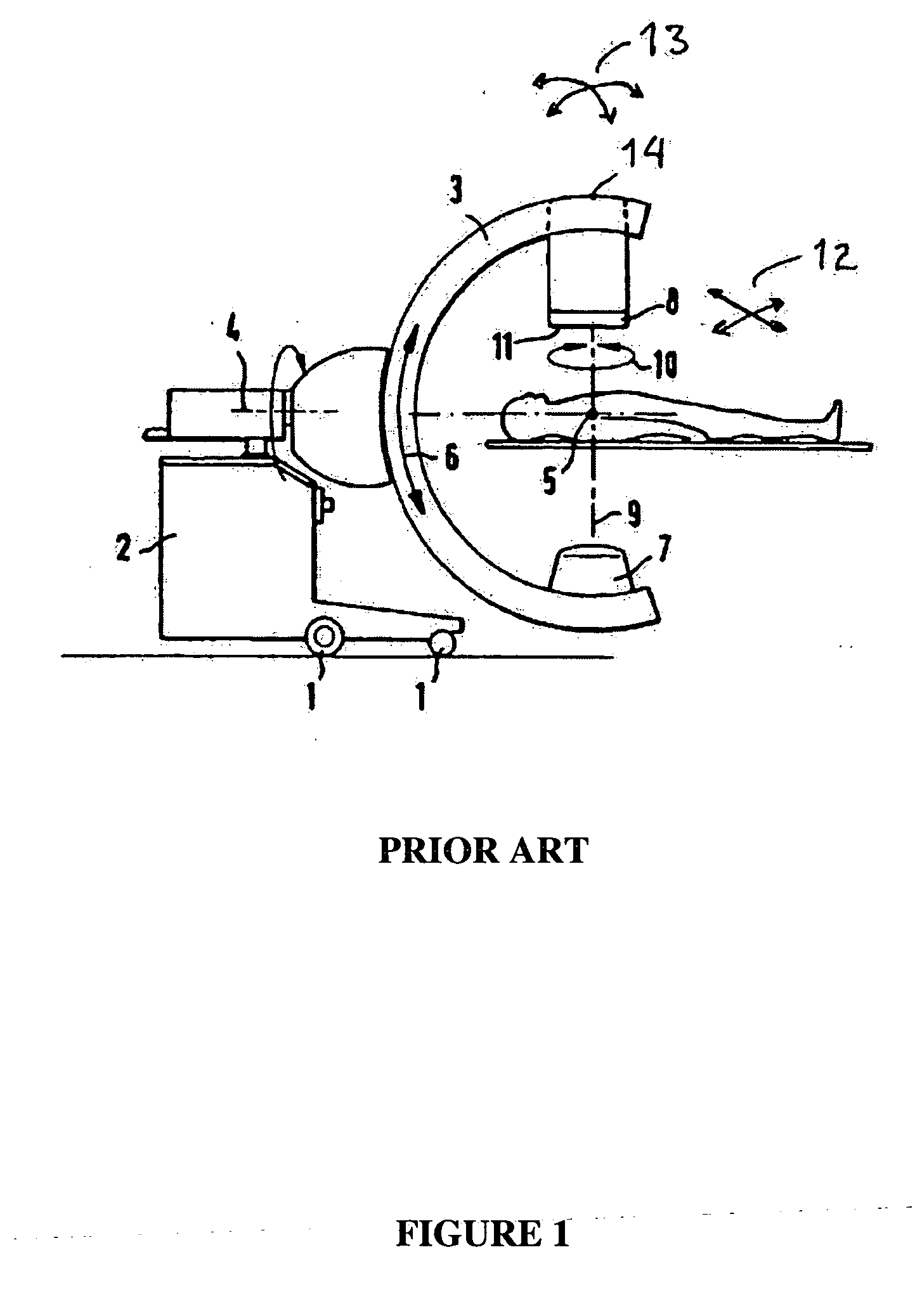
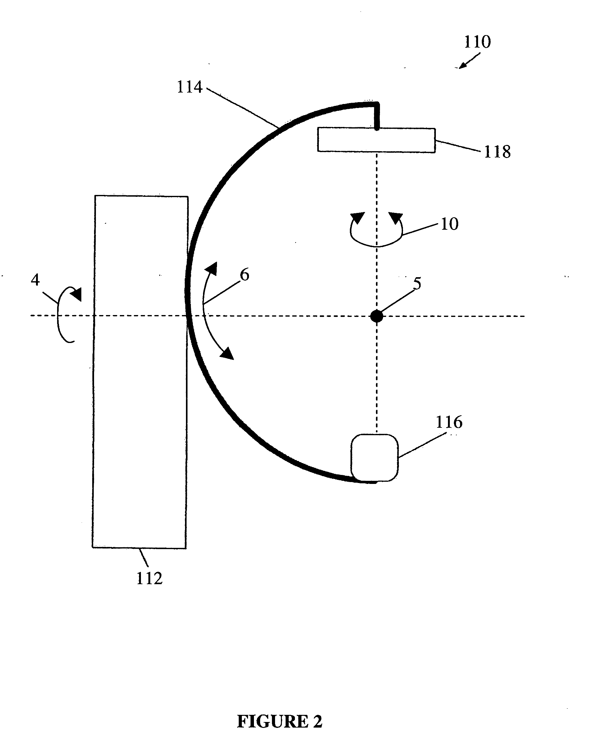
[0025] A C-arm x-ray imaging system acquires two dimensional x-ray projections and it may reconstruct associated three dimensional volumes internal to a patient. If the detector is too small to fully capture the patient's x-ray projections at the detector, reconstructed images suffer from artifacts. In that case, the imaging system may reconstruct enhanced images by creating an effective x-ray detector of greater size that may reduce truncation errors. The x-ray detector may include a movable stage and a detector mount. The movable stage may be movable within the x-ray detector mount. A first partial circular scan may be performed with the movable stage at a first position. Subsequently, the movable stage may be repositioned to a second position before performing a second partial circular scan. By performing two or more partial circular scans with the movable stage located at different positions, the effective size of the x-ray detector may be enlarged, because associated x-ray proj...


PUM


Abstract

A C-arm x-ray imaging system enhances reconstructed volumes internal to a patient. Truncation artifacts in reconstructed volume data sets may be reduced by creating an effective x-ray detector of greater size. The x-ray detector may include a movable stage and a detector mount. The movable stage may be movable within the x-ray detector mount. A first partial circular scan may be performed with the movable stage at a first position. The movable stage may be repositioned to a second position before a second partial circular scan is performed. Performing two partial circular scans with the movable stage located at different positions may increase the effective size of the x-ray detector. The associated views acquired with the detector in opposite offset positions are combined and used for 3D reconstruction. A method of calibration may include generating first and second projection matrices associated with first and second transform parameters, respectively.

Description

PRIORITY CLAIM TO RELATED APPLICATION [0001] This application is a continuation-in-part of and claims priority to prior application Ser. No. 11 / 140,225, filed May 27, 2005, the disclosure of which is incorporated by reference in its entirety herein.BACKGROUND [0002] The present embodiments relate generally to C-arm x-ray systems used for medical imaging. In particular, the present embodiments relate to the correction of truncated projections that may occur with C-arm x-ray imaging systems. [0003] C-arm imaging systems are currently used in medical applications to create both two dimensional x-ray projections and three dimensional tomographically reconstructed images (volume data sets). Conventional C-arm imaging systems, like other cone-beam imaging devices, may be equipped with x-ray detectors that are too small to fully capture a projection of a given object. Typical x-ray detectors may create truncated projections when recording views of objects that extend beyond the boundaries ...

Claims


Application Information

Patent Timeline
IPC IPC(8): H05G1/02A61B6/00A61B6/02A61B6/03G01N23/00G01N23/04G06T11/00
CPCA61B6/032A61B6/4085G01N23/04A61B6/583A61B6/4441A61B6/4452A61B6/5205G06T11/005G06T2211/432G06T11/00
Inventor STROBEL, NORBERT KARL
Owner SIEMENS MEDICAL SOLUTIONS USA INC
Why Eureka
Try Eureka