Optical alignment of cameras with extended depth of field

a technology of depth of field and optical alignment, applied in the field of optical alignment of imaging devices, can solve the problem of complicated finding the optimal working point, and achieve the effect of facilitating image reconstruction

Active Publication Date: 2008-12-25
DIGITALOPTICS CORPORATION
View PDF10 Cites 7 Cited by
  • Summary
  • Abstract
  • Description
  • Claims
  • Application Information

AI Technical Summary

Benefits of technology

[0007]In some devices, however, such as cameras with extended depth of field, finding the optimal working point is more complicated, because the optics may be designed to give roughly uniform focal resolution over a large range of object distances. Furthermore, to facilitate image reconstruction by the deconvolution engine, the optics may be intentionally designed to give a blurred image. Embodiments of the present invention that are described hereinbelow provide methods and systems for calibration that can be useful in overcoming these difficulties.

Problems solved by technology

In some devices, however, such as cameras with extended depth of field, finding the optimal working point is more complicated, because the optics may be designed to give roughly uniform focal resolution over a large range of object distances.

Method used


Image

  • Optical alignment of cameras with extended depth of field
  • Optical alignment of cameras with extended depth of field
  • Optical alignment of cameras with extended depth of field

Examples


Embodiment Construction

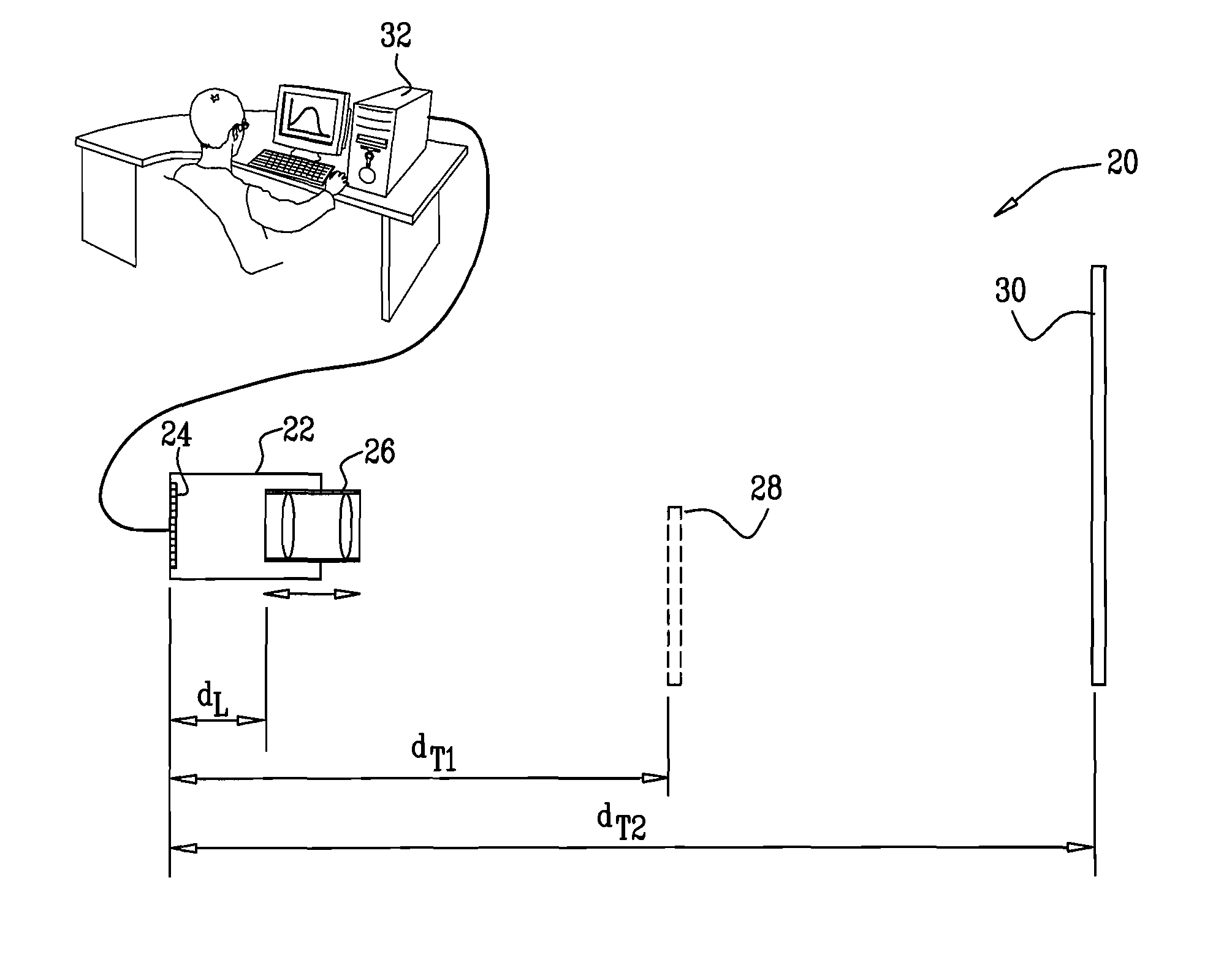
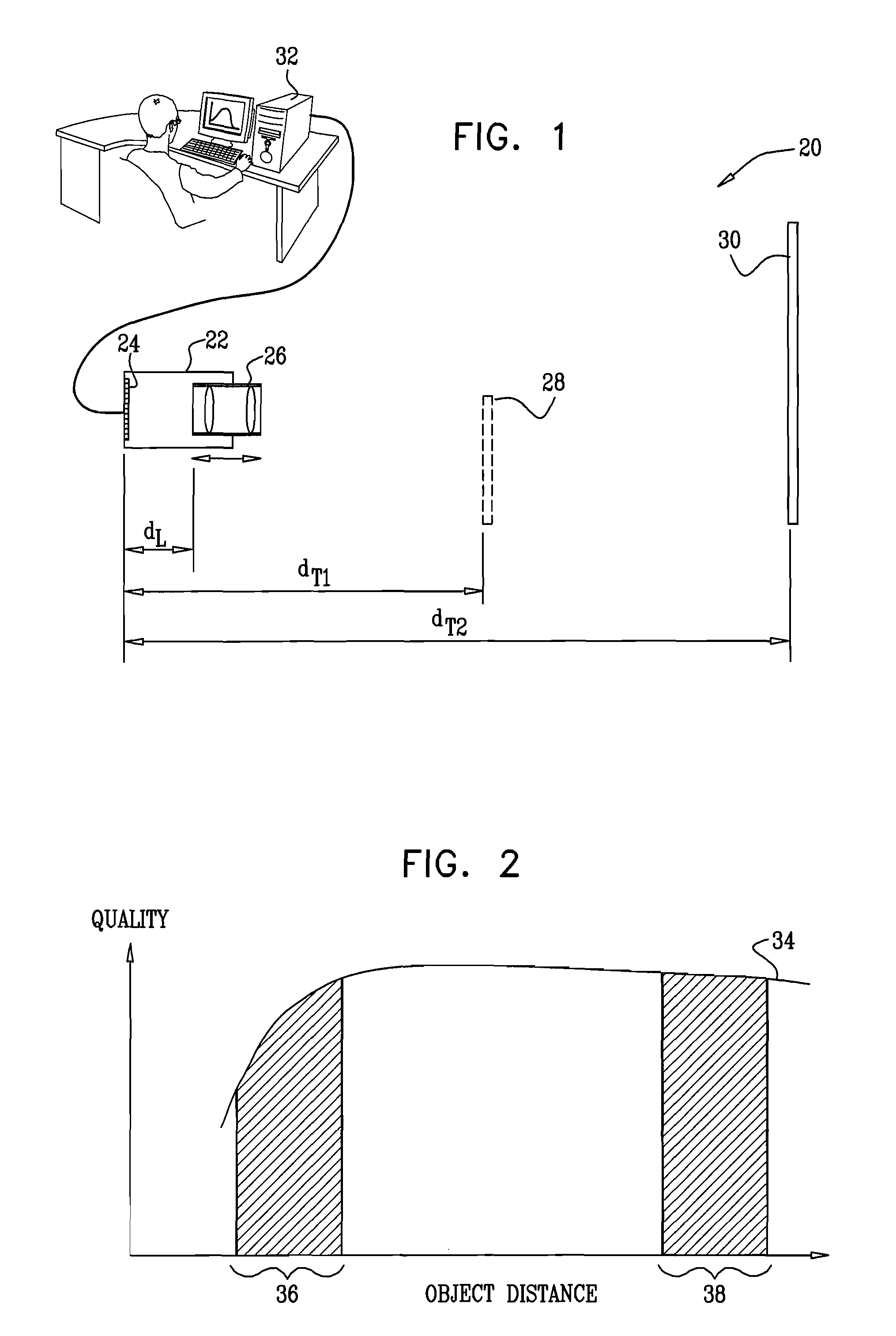
[0037]As noted earlier, in devices with extended depth of field, such as the camera described in the above-mentioned WO 2007 / 054938, adjusting the optics to the optimal working point may be difficult or impossible using a conventional optical calibration procedure. The optimal working point may not be the point of sharpest focus, and even if it is, the change in focal quality as a function of position of the optics may be very gradual. Consequently, it may be difficult to identify the point of sharpest focus with sufficient accuracy to provide the desired level of precision in optical adjustment.

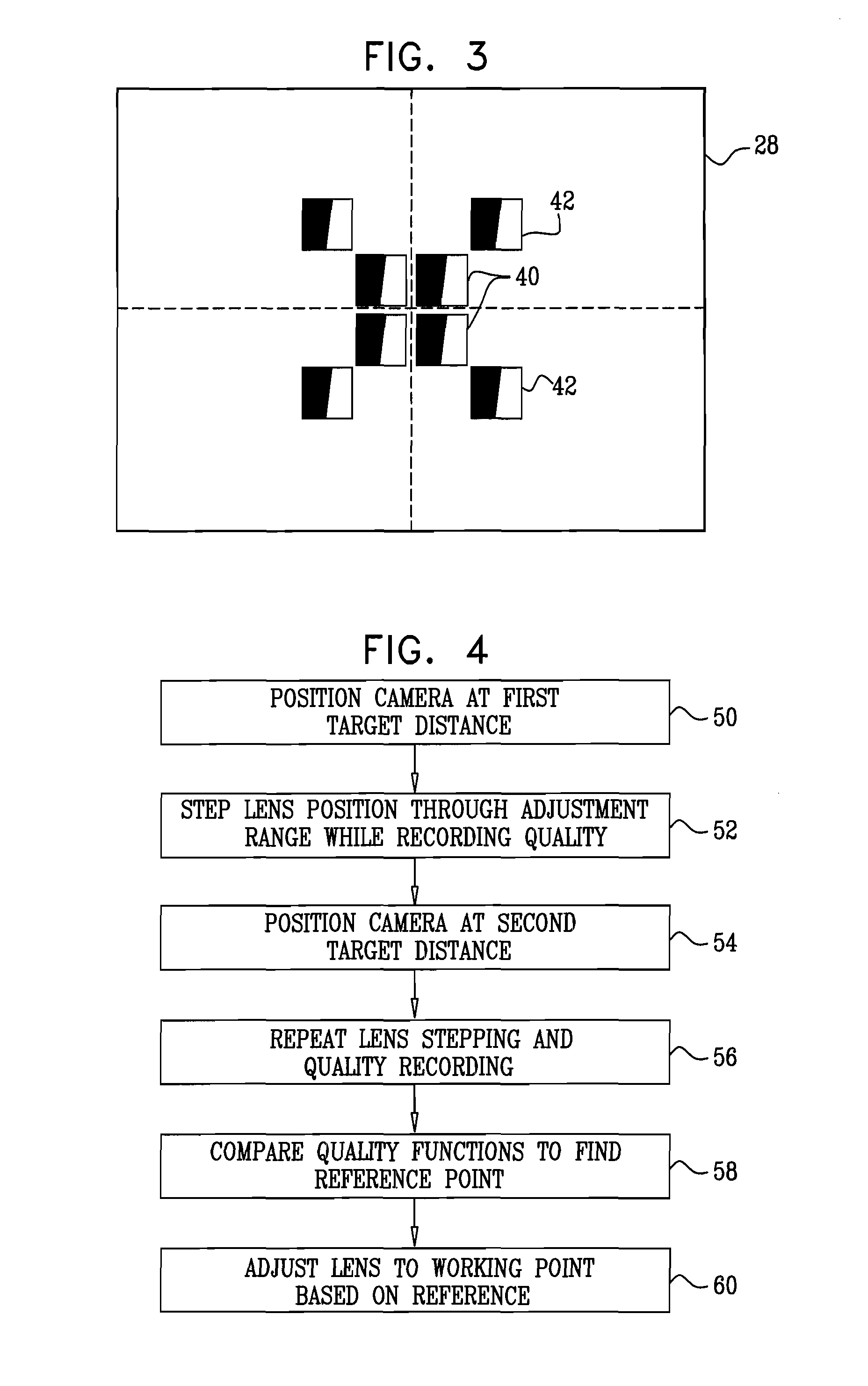
[0038]In some embodiments of the present invention, as a part of a solution to this problem, calibration procedures first find a predefined “reference point” of the optics in the imaging device under calibration, rather than immediately finding the “working point.” The reference point is defined as a known position of the optics, which can be found and measured accurately and repeatably, but...


PUM


Abstract

A method for calibration of an imaging device that includes a sensor and optics for forming an image on the sensor. The method includes making a first image quality measurement, based on an output of the sensor, while imaging a first target at a first distance from the device and varying an offset between the optics and the sensor. A second image quality measurement is made while imaging a second target at a second distance from the device, which is different from the first distance, and varying the offset between the optics and the sensor. A working point of the optics is set relative to the sensor responsively to the first and second image quality measurements.

Description

CROSS-REFERENCE TO RELATED APPLICATION[0001]This application claims the benefit of U.S. Provisional Patent Application 60 / 931,721, filed May 24, 2007, which is incorporated herein by reference.FIELD OF THE INVENTION[0002]The present invention relates generally to imaging devices, and specifically to methods and systems for optical alignment of imaging devices.BACKGROUND OF THE INVENTION[0003]The objective optics used in most digital cameras are typically designed so as to minimize the optical point spread function (PSF) and maximize the modulation transfer function (MTF) of the optics, subject to the limitations of size, cost, aperture size, and other factors imposed by the camera manufacturer.[0004]On the other hand, the optics in some imaging systems, such as certain digital cameras with extended depth of field, are intentionally designed in a manner that does not meet these criteria. For example, PCT International Publication WO 2007 / 054938, whose disclosure is incorporated herei...

Claims


Application Information

Patent Timeline
Patent Type & Authority Applications(United States)
IPC IPC(8): H04N17/00
CPCH04N17/002
Inventor WEISSMAN, LIRON NUNEZKINROT, URIALON, ALEXALON, IRINA
Owner DIGITALOPTICS CORPORATION
Why Eureka
Try Eureka