
Vibe-based three-dimensional sonar point cloud image segmentation method

a three-dimensional sonar and image segmentation technology, applied in image enhancement, image analysis, instruments, etc., can solve the problem of inevitably appearing noise points in the point cloud data, and achieve the effect of reducing the influence of equipment and environmental noise, reducing the workload of subsequent processing, and improving data validity

Active Publication Date: 2021-02-18
ZHEJIANG UNIV
View PDF0 Cites 2 Cited by
  • Summary
  • Abstract
  • Description
  • Claims
  • Application Information

AI Technical Summary

Benefits of technology

The present invention provides a simple and efficient method for segmenting a ViBe-based three-dimensional sonar point cloud image. This method can effectively segment the foreground and background data, reducing noise and improving the quality of the image. The method uses a group of thresholds, which helps to accurately segment the voxels to either the foreground or background data. This can be done selectively before processing a large amount of data, improving the data validity and reducing the processing workload. The method is also flexible and practical, as it can be easily adjusted based on different equipment and environments without changing the program of the system. Overall, this method is highly efficient, rapid, and meets real-time requirements.

Problems solved by technology

However, during acquiring three-dimensional sonar point cloud data, some noise points will inevitably appear in the point cloud data due to the influence of changes in the surface properties of measured objects and data mosaicking and registration operation process as well as the influence of equipment accuracy, operator experience, underwater environmental factors, etc.
In practice, in addition to those noise points generated by measurement random errors, there are often some discrete points, namely outliers, far away from the main point (the measured object point), in the point cloud data as a result of the influence of external interference such as obstacles.

Method used


Image

  • Vibe-based three-dimensional sonar point cloud image segmentation method

Examples


Embodiment Construction

[0032]For more clarity of the objects, technical solutions, and advantages in the present invention, the present disclosure is described in details below with reference to the accompanying drawings and embodiments. It should be understood that the embodiments described herein are only for explaining the present invention, but not for limiting the present invention.

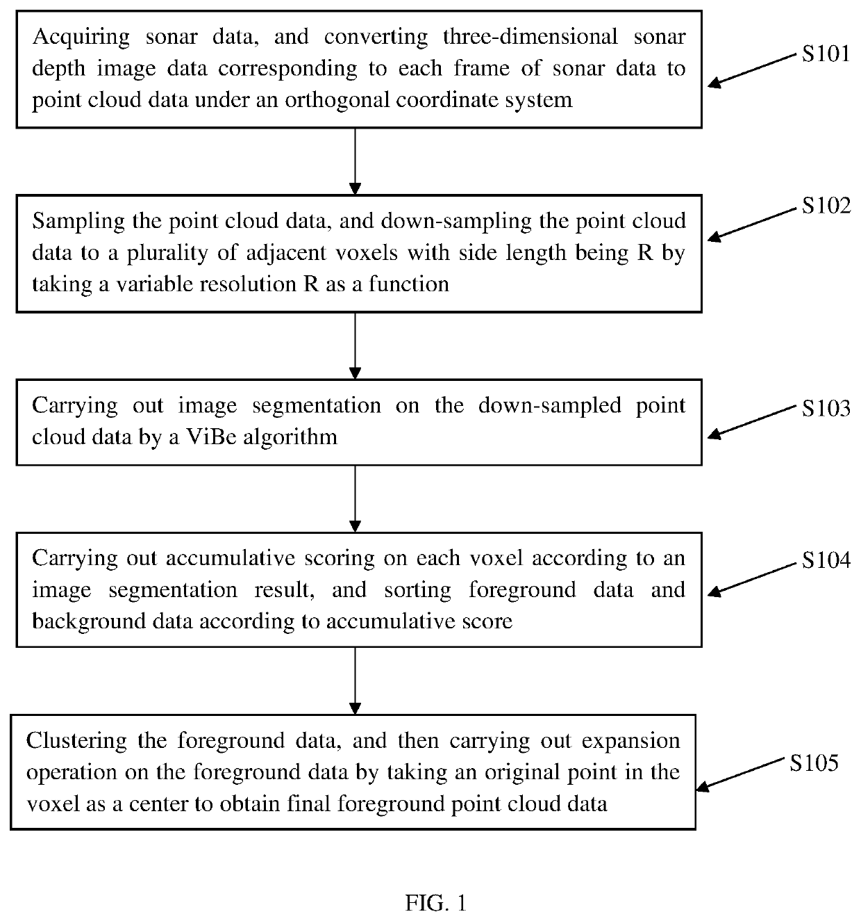
[0033]FIG. 1 is a flow chart of a ViBe-based three-dimensional sonar point cloud image segmentation method provided by an embodiment of the present invention. As shown in FIG. 1, the three-dimensional sonar point cloud image segmentation method provided by the embodiment of the present invention, comprising the following steps:

[0034]In S101, sonar data is acquired, and three-dimensional sonar depth image data corresponding to each frame of sonar data is converted to point cloud data under an orthogonal coordinate system.

[0035]In the embodiment, the three-dimensional sonar depth image data is converted from spherical produc...


PUM


Abstract

The present invention discloses a ViBe-based three-dimensional sonar point cloud image segmentation method, characterized by including: (1) acquiring sonar data, and converting three-dimensional sonar depth image data corresponding to each frame of the sonar data to point cloud data under an orthogonal coordinate system; (2) sampling the point cloud data, and down-sampling the point cloud data to a plurality of adjacent voxels with side length being R by taking a variable resolution R as a function; (3) carrying out image segmentation on the down-sampled point cloud data by a ViBe algorithm; (4) carrying out accumulative scoring on each voxel according to an image segmentation result, and sorting foreground data and background data according to accumulative score; and (5) clustering the foreground data, and then carrying out expansion operation on the foreground data by taking an original point in the voxel as a center to obtain final foreground point cloud data.

Description

TECHNICAL FIELD[0001]The present invention belongs to the field of three-dimensional sonar point cloud image processing, and particularly relates to a Visual Background Subtraction (ViBe) based sonar point cloud image segmentation method.BACKGROUND[0002]The phased array three-dimensional sonar system is a new underwater three-dimensional acoustic imaging system and can be widely applied in aspects of real-time port monitoring, underwater operation of frogmen, etc.[0003]However, during acquiring three-dimensional sonar point cloud data, some noise points will inevitably appear in the point cloud data due to the influence of changes in the surface properties of measured objects and data mosaicking and registration operation process as well as the influence of equipment accuracy, operator experience, underwater environmental factors, etc. In practice, in addition to those noise points generated by measurement random errors, there are often some discrete points, namely outliers, far awa...

Claims


Application Information

Patent Timeline
Patent Type & Authority Applications(United States)
IPC IPC(8): G06T7/194G06T7/11G06T7/136G06V10/28
CPCG06T7/194G06T2207/10028G06T7/136G06T7/11G06F18/23G06T5/70G06T7/187G06V20/64G06V10/28
Inventor CHEN, YAOWUTIAN, XIANGLIU, XUESONGJIANG, RONGXIN
Owner ZHEJIANG UNIV
Learn More