Vacuum-seated dentures with skin contacting plate

a technology of skin contact plate and dentures, applied in the field of dentures, can solve the problems of dentures not always fitting perfectly, and achieve the effects of simple hand and finger pump, secure bonding, and convenient installation

a technology of skin contact plate and dentures, applied in the field of dentures, can solve the problems of dentures not always fitting perfectly, and achieve the effects of simple hand and finger pump, secure bonding, and convenient installation

US20060040235A1Inactive Publication Date: 2006-02-23DAVIS JESSE L

Image

  • Vacuum-seated dentures with skin contacting plate
  • Vacuum-seated dentures with skin contacting plate

Examples


Embodiment Construction

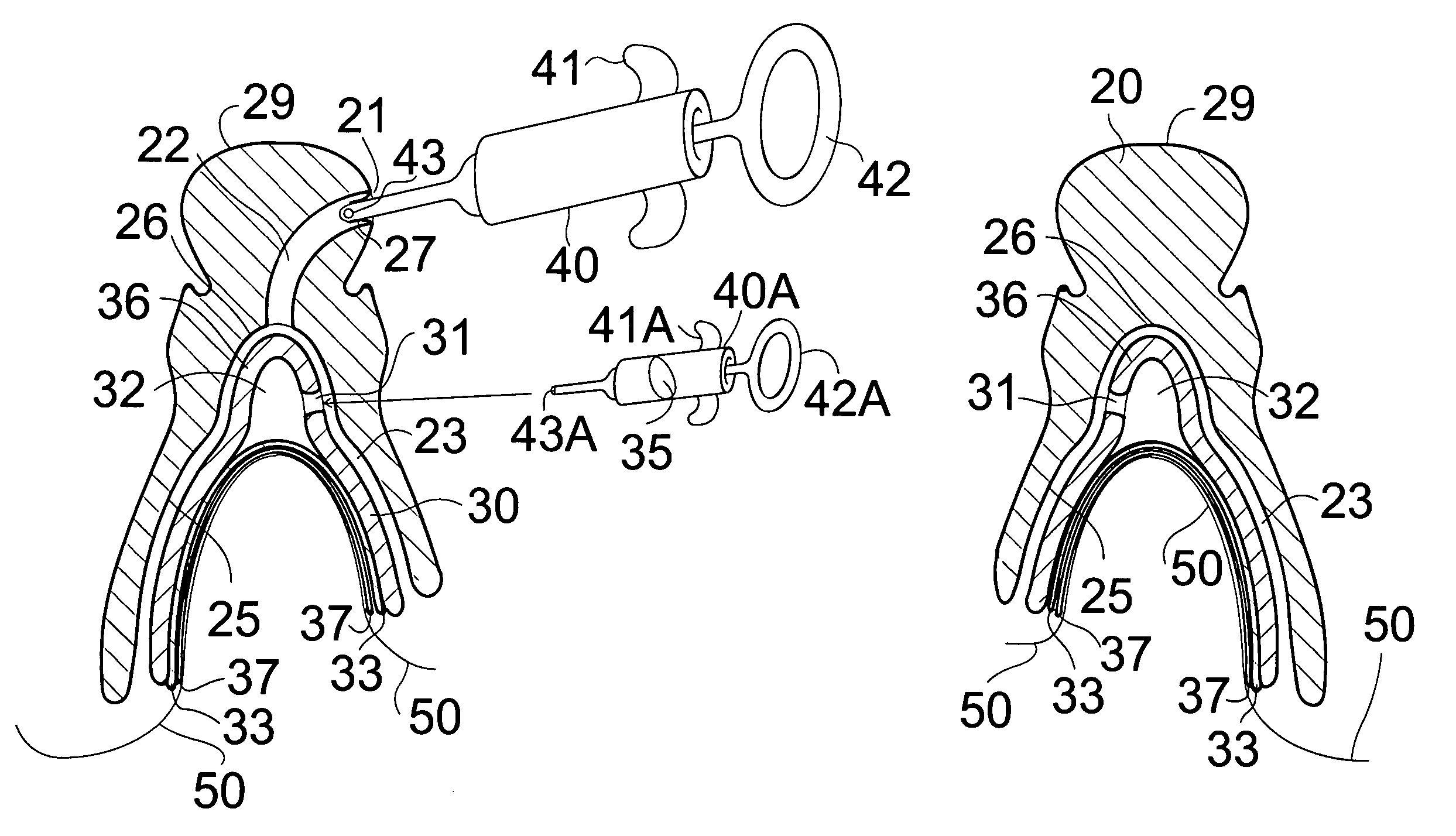
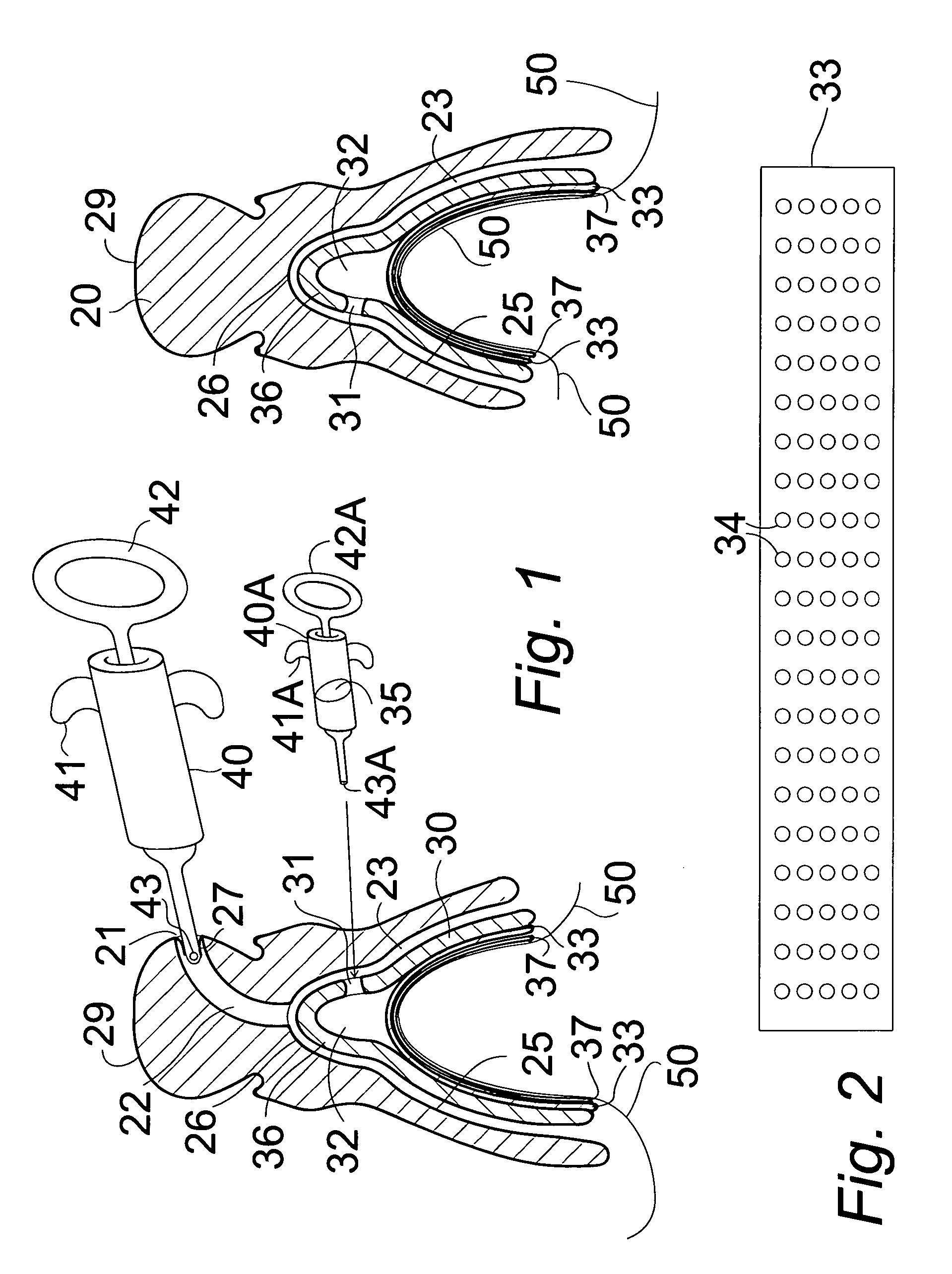
[0036] In FIGS. 1 and 2, a vacuum denture system for secure attachment of dentures comprises a skin contacting plate 30 adhered to the gums 50 and a denture plate 20 secured to the skin contacting plate by a vacuum therebetween.

[0037] In FIG. 1, the skin contacting plate 30, made from a clay mold imprint of the gums, conforms to the shape of the gums 50 and is adapted for securing to the gums with a securing substance, such as a skin adhering compound 37. The skin contacting plate 30 comprises an inner layer 33 or membrane adjacent to the skin of the gums 50 of the wearer, the inner layer 33 having an array of perforations 34 through the inner layer, as seen in FIG. 2, to admit the securing substance, the skin adhering compound 37, therethrough to bond the skin contacting plate 30 to the gums 50. After spreading the skin adhesive onto the perforated bottom of the plate, pressing the plate onto the gums causes the adhesive to spread through the perforations forming little balls or c...


PUM


Abstract

A skin contacting plate is formed in the shape of the gums to which the plate is secured by a skin adhering compound on a perforated layer. A protruding ridge along the teeth line has an internal reservoir to receive a skin adhering compound solvent from a syringe-type liquid pump to dissolve the compound to remove the skin contacting plate when desired. A denture plate conforms to the shape of the skin contacting plate and the protruding ridge. A syringe-type vacuum air pump draws the air from between an internal passageway between the plates through a valve in the denture plate to form a vacuum to maintain the plates together. Pumping air into the internal passageway immediately releases the plates.

Description

BACKGROUND OF THE INVENTION [0001] 1. Field of the Invention [0002] The present invention relates to dentures that are held in place with a vacuum seal, and particularly to dentures with a plate secured to the gums with an adhering compound brushed onto a perforated metal bottom of the plate and an insertable vacuum pump air which draws air out of an internal passageway in the dentures through an automatically sealable air valve in the dentures to evacuate the air from the space between the plate and the dentures creating a strongly attractive vacuum to firmly secure the dentures in place. [0003] 2. Description of the Prior Art [0004] Dentures are substitutes for missing teeth and serve as a replacement for all or some of the teeth found in the oral cavity. Despite diligent efforts by dental professionals and designers of dental prostheses, dentures do not always fit perfectly. Adherent creams, liquids or powders are often used to secure or temporarily fix dentures within the mouth....

Claims


Application Information

Patent Timeline
23 Feb 2006
Publication
US20060040235A1
IPC
A61C13/24
CPC
A61C13/24; A61C13/25; A61C13/245
Inventors
DAVIS, JESSE L.