Main board and fixing component thereof

a technology of fixing components and main boards, which is applied in the manufacture of electrical apparatus construction details, connection contact member materials, and final product manufacturing, etc., can solve the problems of increasing the difficulty of designing the placement of bosses, increasing layout design problems, and increasing the occupied space on the main board. , the effect of saving labor costs

Inactive Publication Date: 2006-02-23
VIA TECH INC
View PDF12 Cites 13 Cited by
  • Summary
  • Abstract
  • Description
  • Claims
  • Application Information

AI Technical Summary

Benefits of technology

[0011] As mentioned above, the fixing component of the main board of the invention is disposed on the main board by utilizing SMT and DIP technology, and has a fixing part requiring a smaller opening on the main board than that of prior art. Therefore, the occupied space on the main board can be reduced, and the disposition of the fixing component can be integrated in a production line with utilizing the SMT and DIP technology. Accordingly, the layout space can be increased and the labor costs can be saved.

Problems solved by technology

Due to the development of the main board with stronger and stronger functions, layouts on the main board are also more and more complicated.
However, the boss will occupy some layout spaces, which results in the problems of the layout design.
Correspondingly, the difficulty of designing the placement of the bosses is increased.
However, the above-mentioned combination method needs to manually assemble the boss with the screw or the nut, so that it wastes many labor costs and time.
Furthermore, if the elements of the product are unstable combined caused by artificial faults, the product may have element separations in the later usage.
However, since the contact area of the boss and the ground point is not enough, this solution may not prevent the EMI efficiently.
It occupies more area on the main board, so that the layout design becomes harder.
Besides, this solution needs to manually combine the elements, which results in the increase of production costs.

Method used


Image

  • Main board and fixing component thereof
  • Main board and fixing component thereof
  • Main board and fixing component thereof

Examples


Embodiment Construction

[0017] The main board and the fixing component thereof of the present invention will be apparent from the following detailed description, which proceeds with reference to the accompanying drawings, wherein the same references relate to the same elements.

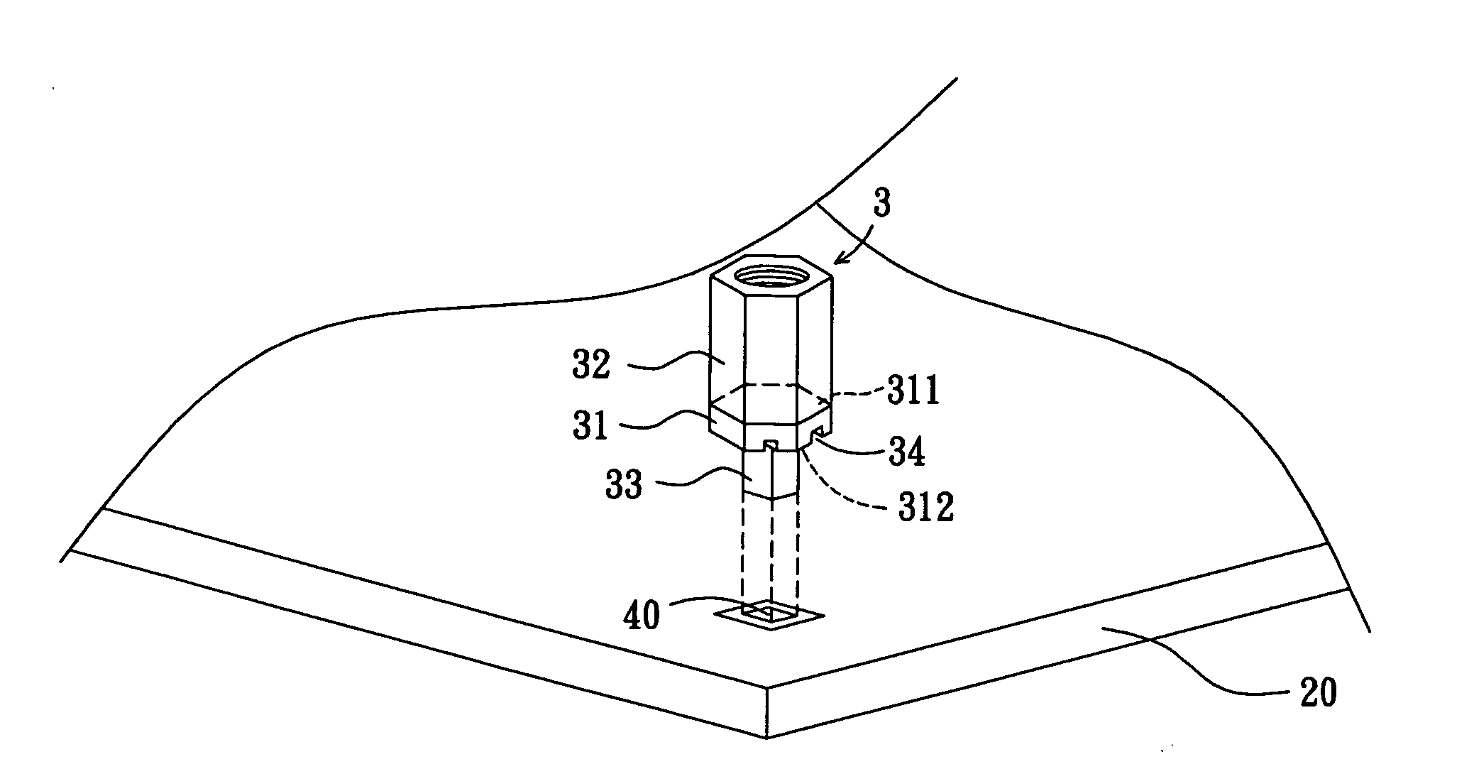
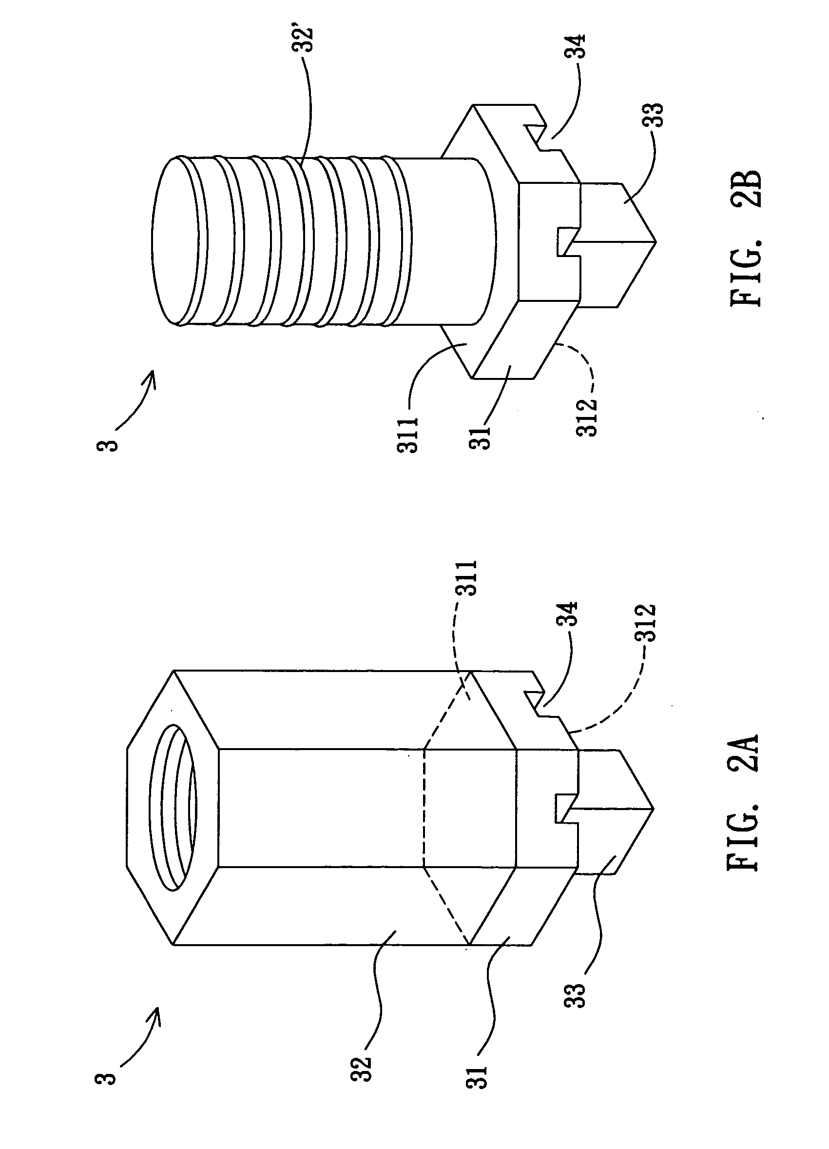
[0018] A fixing component 3 of a main board according to a preferred embodiment of the invention comprises a connecting part 31, a thread-assembling part 32, and a fixing part 33.

[0019] Referring to FIG. 2A, in this embodiment, the materials of the connecting part 31, the thread-assembling part 32, and the fixing part 33 are conductivity materials. The connecting part 31 has a first surface 311 and a second surface 312, which is disposed opposite to the first surface 311 and is formed with at least a groove 34 thereon.

[0020] The thread-assembling part 32 is disposed on the first surface 311 of the connecting part 31. In this embodiment, the thread-assembling part 32 is a female thread-assembling part, which is used to connect with...


PUM


Abstract

A fixing component of a main board comprises a connecting part, a thread-assembling part and a fixing part. The connecting part has a first surface and a second surface, wherein the first surface is disposed opposite to the second surface. The thread-assembling part is disposed on the first surface of the connecting part. The fixing part is disposed on the second surface. The connecting part and the fixing part are disposed on a main board by utilizing DIP technology and SMT.

Description

BACKGROUND OF THE INVENTION [0001] 1. Field of Invention [0002] The invention relates to a main board and a fixing component thereof and, in particular, to a fixing component, which is disposed on a main board by utilizing the surface mounted technology (SMT) and dual inline package (DIP) technology. [0003] 2. Related Art [0004] In general, there are many bosses with different size disposed on the main board. The efficiency of these bosses is to cooperate with a case to fix the main board or to fix other additional elements, which must be fixed on the main board. Due to the development of the main board with stronger and stronger functions, layouts on the main board are also more and more complicated. However, the boss will occupy some layout spaces, which results in the problems of the layout design. Correspondingly, the difficulty of designing the placement of the bosses is increased. [0005] Referring to FIG. 1A, the combination method of the conventional boss includes the followi...

Claims


Application Information

Patent Timeline
Patent Type & Authority Applications(United States)
IPC IPC(8): H01R12/00
CPCH01R4/64H05K3/341H05K7/142H01R12/707H05K2201/10409H05K2201/10598H05K2201/0373Y02P70/50
Inventor KUO, KEVINHSYU, JAMESCHANG, LANGHANS
Owner VIA TECH INC
Why Eureka
Try Eureka