Measurement electronic device system

a technology of electronic devices and measurement devices, applied in the direction of electric programme control, instruments, program control, etc., can solve the problems of inability to speed up the measurement time, increase the cost of the system, so as to achieve high-reliability measurement results and enhance simultaneity of measurements

Inactive Publication Date: 2006-02-23
CITIZEN WATCH CO LTD
View PDF8 Cites 33 Cited by
  • Summary
  • Abstract
  • Description
  • Claims
  • Application Information

AI Technical Summary

Benefits of technology

[0021] The present invention was made to solve the above-described problems, and an object thereof is to enhance simultaneity of measurements by a plurality of measurement electronic device units so that a highly reliable measurement result can be obtained.

Problems solved by technology

A specialized circuit has to be provided in order to allow the controller 150 to simultaneously read the values measured by all the measurement electronic device units 101 to 104, which poses problems that the system becomes complicated and expensive.
This method, however, has a problem that the rotation speed of the camshaft 120 is not allowed to be high and thus it is not possible to speed up the measurement time.
Moreover, since the rolled iron plate moves up and down, each of the measured values of the two detectors, if individually seen, often presents a larger change than the change of the plate thickness.
Thus, when a measured object is moving, it is important that the measured values of the two detectors are simultaneously measure values, and if their measurements are not simultaneous, the measured values become more unreliable.
However, in a system in which an external device such as a personal computer reads values measured by two measurement electronic device units to calculate the sum thereof, a read operation of the measured value is performed twice, and time lag therebetween deteriorates reliability of the measured values.
This poses a problem that the wiring becomes complicated.
However, reading the measured values by an operator has not only a problem of complicating the work but also a problem of operation mistakes that the operator might make.
The arithmetic operation by the external device results in a heavy load on the external device, and also results in poor operability especially in maintenance work since the operation result cannot be visually confirmed.

Method used


Image

  • Measurement electronic device system
  • Measurement electronic device system
  • Measurement electronic device system

Examples


Embodiment Construction

[0051] Preferred embodiments of the invention will be described with reference to the accompanying drawings for more detailed description of the invention.

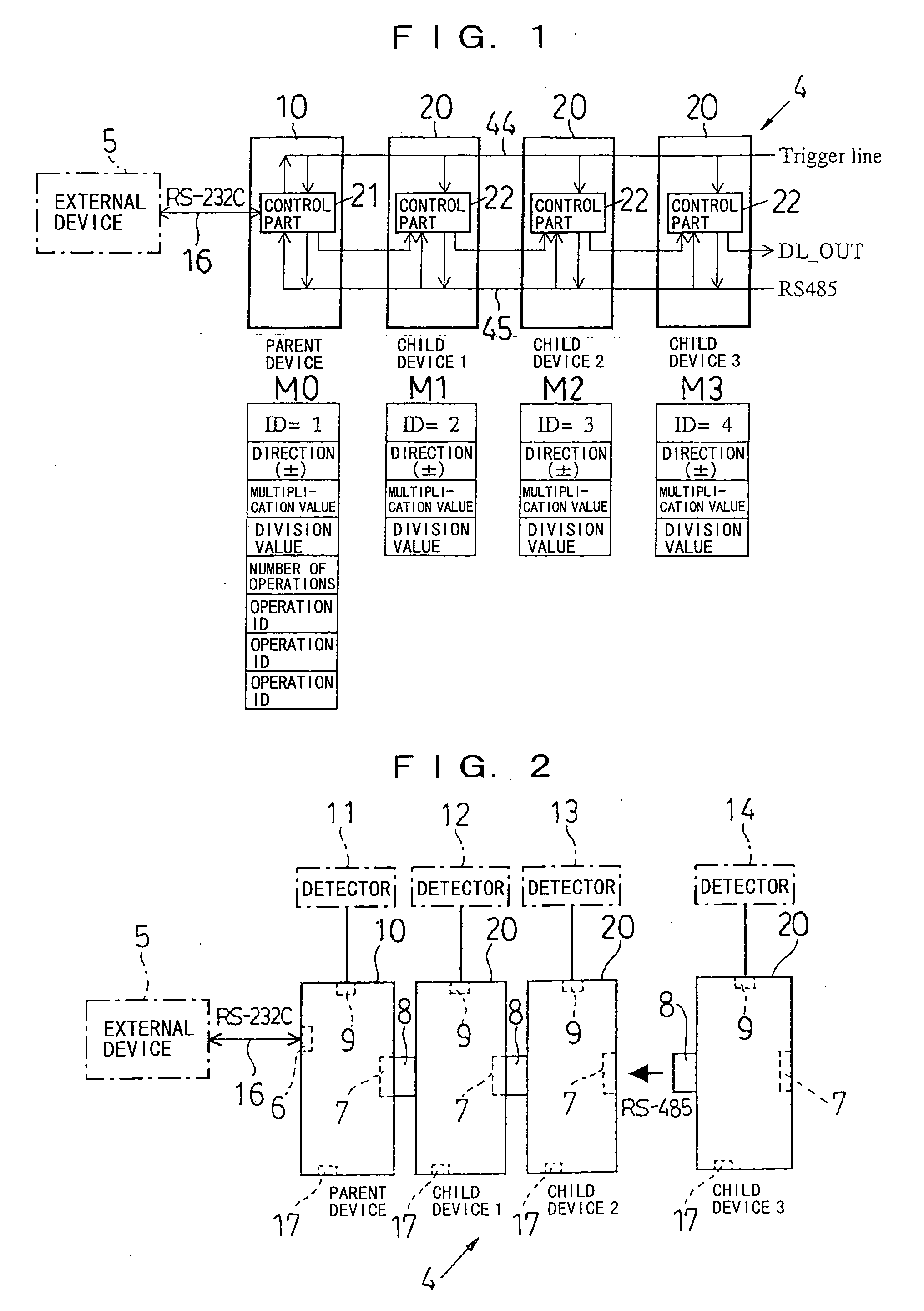
[0052] First, a schematic configuration of one embodiment of a measurement electronic device system according to the invention will be described with reference to FIG. 2.

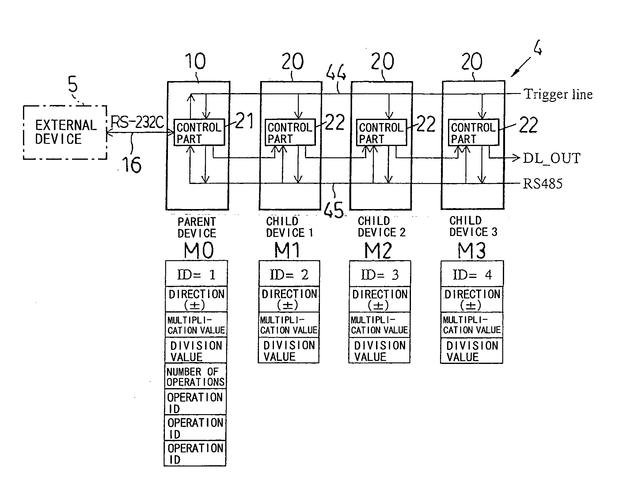
[0053] This measurement electronic device system is comprised of four measurement electronic device units. Among them, a measurement electronic device unit 10 is a parent device which includes: a female connector (for external device interface) 6 for connection to an external device 5 having a data processing function; and a female connector (for downstream device interface) 7 for connection to the other electronic device unit (child device) and thus has a function of transmitting / receiving data and signals to / from the external device 5.

[0054] The other measurement electronic device units 20 are child devices, each including two connectors for connection to the...


PUM


Abstract

A plurality of measurement electronic device units (10, 20) each having a measurement detector connected thereto and thus having a measuring function are connected in series by connectors to be capable of mutually conveying measurement data and signals, and one (10) of the plural measurement electronic device units serves as a parent device having a function of transmitting/receiving measurement data and signals to/from an external device (5). Each of the control parts (21, 22) of the plural measurement electronic device units (10, 20) has a memory storing a measured value, and the parent device sends a measured value save command to a trigger line (44) in response to a request from the external device (5) to the parent device so that the measurement electronic device units including the own unit are caused to simultaneously save measured values in the control parts (21, 22).

Description

TECHNICAL FIELD [0001] The invention relates to a measurement electronic device system comprising: a measurement electronic device unit (parent device) capable of transmitting / receiving data to / from an external device; and a plurality of measurement electronic device units (child devices) connected in series to the parent device. BACKGROUND TECHNOLOGY [0002] In order to obtain desired measurement data, widely practiced is a method in which a plurality of measurement electronic device units each having a measurement detector connected thereto and thus having a measurement function are used, and a common control device (a controller, a personal computer, or the like) controls these units to collect and process the measurement results by the respective measurement electronic device units. [0003] In order to measure, for example, the shape of a camshaft being an engine part of an automobile, it is necessary to measure displacements of respective cams provided in the camshaft at each rot...

Claims


Application Information

Patent Timeline
Patent Type & Authority Applications(United States)
IPC IPC(8): G06F19/00G01D9/00G01D9/28G01D21/02G08C15/06
CPCG01D21/02G01D9/005
Inventor KUWAYAMA, KENJISEGAWA, AKIO
Owner CITIZEN WATCH CO LTD
Why Eureka
Try Eureka