Method of detecting data in detection apparatus and detection apparatus

A technology of data detection and detection devices, which is applied in the direction of measuring devices, using electric/magnetic devices to transmit sensing components, converting sensor outputs, etc., which can solve the problems of time difference and the inability to obtain the angular position of magnets with high precision

Active Publication Date: 2015-04-29
SANKYO SEIKI MFG CO LTD
View PDF5 Cites 1 Cited by
  • Summary
  • Abstract
  • Description
  • Claims
  • Application Information

AI Technical Summary

Problems solved by technology

[0006] However, in Figure 7 In the oversampling shown, since the arithmetic mean of the A-phase data corresponds to the data at time t3, and the arithmetic mean of the B-phase data corresponds to the data at time t4, the arithmetic mean of the A-phase data corresponds to the B-phase data There is a time difference between the arithmetic means of
Therefore, there is a problem that the angular position of the magnet relative to the magnetic sensor device cannot be obtained with high precision when calculating the arc tangent from the A-phase data and the B-phase data.

Method used


Image

  • Method of detecting data in detection apparatus and detection apparatus
  • Method of detecting data in detection apparatus and detection apparatus
  • Method of detecting data in detection apparatus and detection apparatus

Examples


Embodiment Construction

[0046] Hereinafter, a detection device to which the present invention is applied will be described focusing on a rotary encoder with reference to the drawings. In addition, in the rotary encoder, when detecting the rotation of the rotating body relative to the fixed body, it is possible to adopt a structure in which a magnet is provided on the side of the fixed body and a magnetoresistive element is provided on the side of the rotating body, or a magnetic resistance element is provided on the side of the fixed body. In the structure in which a magnet is provided on the rotating body side instead of a resistive element, the following description will focus on a structure in which a magnetic sensor is provided on the fixed body side and a magnet is provided on the rotating body side.

[0047] [Outline structure of rotary encoder]

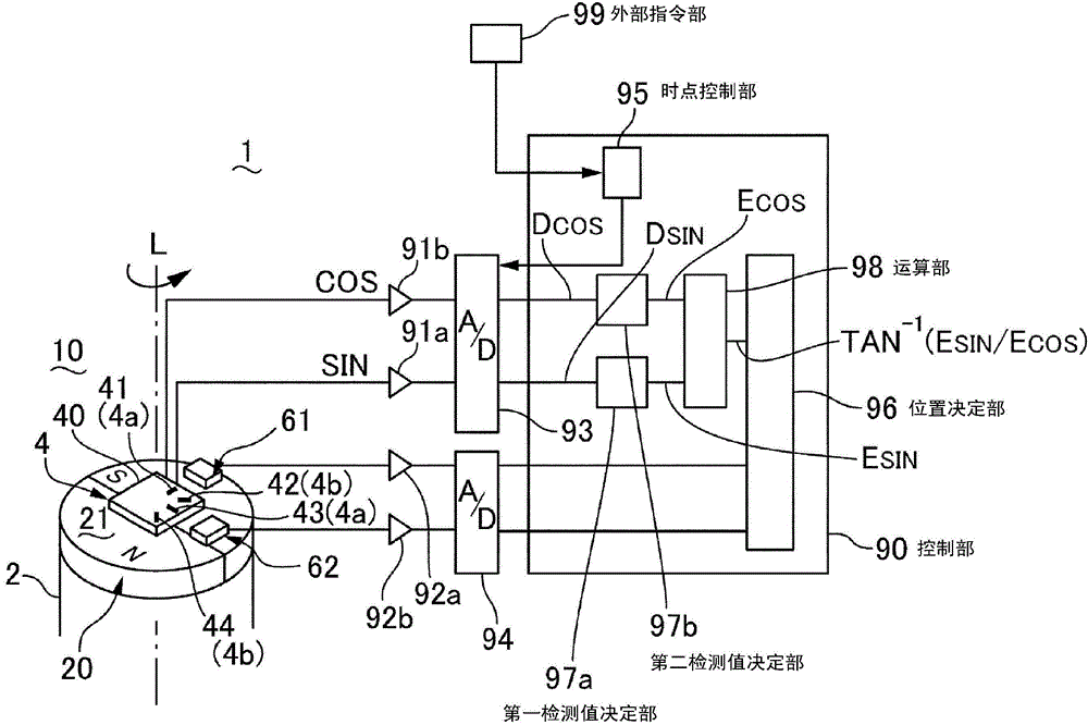
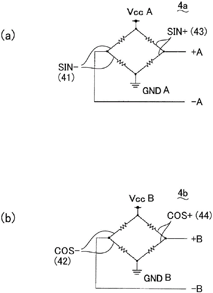
[0048] figure 1 It is an explanatory diagram of the rotary encoder 1 to which the present invention is applied. figure 2 It is an explanatory dia...


PUM


Abstract

The invention provides a method of detecting data in detection apparatus and a detection apparatus which can improve simultaneity of data from two detection parts. In a rotary encoder, the times of obtaining first data (Dsin) and second data (Dcos) in a data detection period (T) is greater than three, such as five. During such over-sampling, as the times of obtaining the first data (Dsin) and the second data (Dcos) is greater than three, the arithmetic mean of the first data (Dsin) obtained at the time points of odd number times is used to determine a first detection value (Esin); the arithmetic mean of the second data (Dcos) obtained at the time points of even number times is used to determine a second detection value (Ecos); and the first detection value (Esin) and the second detection value (Ecos) are both corresponding to a time (t3) in the middle of the data detection period (T).

Description

technical field [0001] The present invention relates to a data detection method and a detection device of a detection device such as a rotary encoder. Background technique [0002] In a rotary encoder that detects rotation of a rotating body relative to a fixed body, for example, a magnetic sensor device (detection device) having a magnet on the side of the rotating body and a magnetoresistive element or Hall sensor on the side of the fixed body is provided. Seoul components. In such a magnetic sensor device, for example, in a magnetic sensor device having a magnetoresistive element, a magnetoresistive film is formed on one side of a substrate, and based on The two outputs output by the bridge circuit detect the angular velocity, angular position, etc. of the rotating body (for example, refer to Patent Document 1). [0003] that is, Figure 7 As shown, since the output of phase A represents a sine wave, and the output of phase B represents a cosine wave, if the arc tangent...

Claims


Application Information

Patent Timeline
Patent Type & Authority Applications(China)
IPC IPC(8): G01D5/12
CPCG01D5/125G01D5/00G01D5/12G01D5/245
Inventor 海老根徹奥村宏克小田切秀行常田晴宏
Owner SANKYO SEIKI MFG CO LTD
Why Eureka
Try Eureka