Repair of turbines on wing

a technology for repairing turbine engines and wing wings, which is applied in the direction of turbines, machines/engines, manufacturing tools, etc., can solve the problems of increasing the cost of demurrage, and increasing the cost of gas turbine engines

Inactive Publication Date: 2006-03-02
HONEYWELL INT INC
View PDF24 Cites 79 Cited by
  • Summary
  • Abstract
  • Description
  • Claims
  • Application Information

AI Technical Summary

Benefits of technology

[0009] The present invention provides a miniaturized laser apparatus and related components. The laser may be directed onto a workpiece such as a turbine blade through a fiber optic cable. The flexibility and size of the fiber optic cable allow it to be directed from the engine exterior to the interior of a gas turbine engine through inspection ports or “borescope holes”. Likewise feed apparatus such as powder feeders or wire feeders may also be directed from the engine exterior to the interior. Additionally visualization and illumination is brought to the workpiece through a mechanism such as a borescope. With this apparatus laser welding repairs can be performed without the need of either removing the gas turbine engine from the aircraft body or disassembling the gas turbine engine.

Problems solved by technology

Gas turbine engines have a number of complex components that require periodic inspection.
Demurrage costs and lost revenue potential that arises when an aircraft is out of service add to that cost.
Maintenance is typically a scheduled event whereas unexpected repairs may also arise on an unscheduled basis.
Furthermore, certain detailed engine work also requires disassembling, or partially disassembling, the engine.
Over and above the cost of the repair, this kind of work is lengthy and expensive in that it requires removing the aircraft from service.
It further requires the lengthy process of disassembling and then reassembling the engine.
These materials of which modern turbine blades are often fabricated are difficult to weld.
However, the prior art methods of laser welding repair are disadvantageous for several reasons, particularly in terms of aircraft management.
Heretofore, laser welding equipment has been relatively large and bulky.
And that requires taking the airplane out of service for an extended time.
However, these devices still suffer from shortcomings and limitations.
The newer laser welding machines have not had the mobility that would allow them to be moved into a repair area.
Further compact laser welding machines have also suffered from a lack of sufficient power.

Method used


Image

  • Repair of turbines on wing
  • Repair of turbines on wing
  • Repair of turbines on wing

Examples


Embodiment Construction

[0019] The following detailed description of the invention is merely exemplary in nature and is not intended to limit the invention or the application and uses of the invention. Furthermore, there is no intention to be bound by any theory presented in the preceding background of the invention or the following detailed description of the invention. Reference will now be made in detail to exemplary embodiments of the invention, examples of which are illustrated in the accompanying drawings. Wherever possible, the same reference numbers will be used throughout the drawings to refer to the same or like parts.

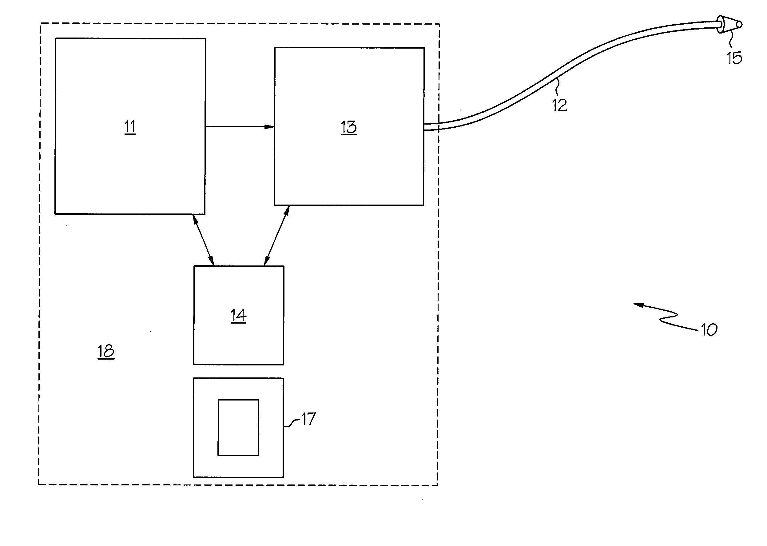
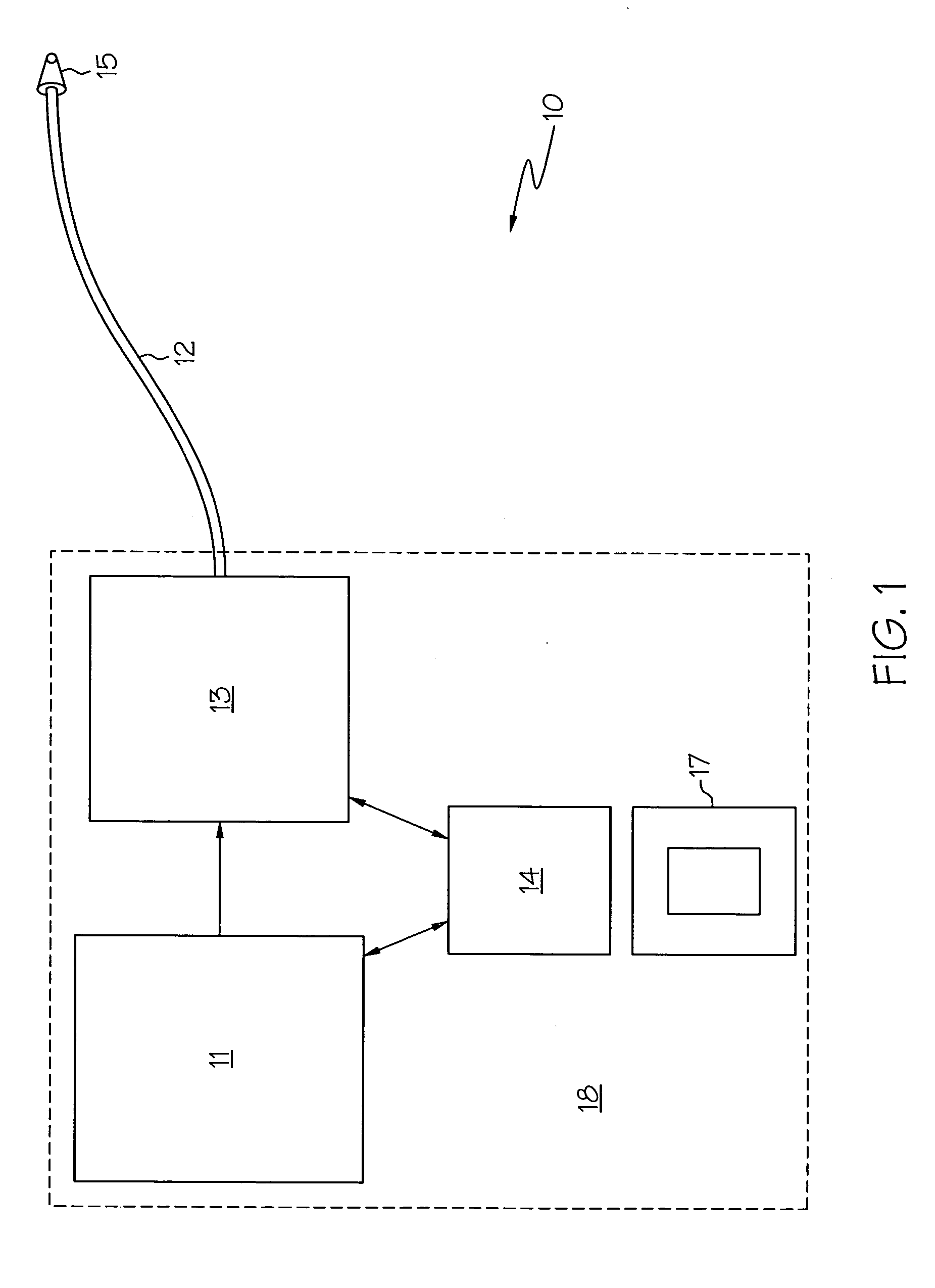
[0020] It has now been discovered that repairs and maintenance, including laser repairs, can be conducted at points in the interior of a gas turbine engine. It has been conceived to bundle the means to remotely view objects, convey laser power, and manipulate the direction of viewing and laser power by combining these means at the tip of a flexible conveyance. The flexible conveyan...


PUM

PropertyMeasurementUnit
areaaaaaaaaaaa
areaaaaaaaaaaa
poweraaaaaaaaaa

Abstract

The present invention provides an apparatus for repairing turbine blades of a gas turbine engine by a laser welding operation. The method uses a miniaturized laser and related apparatus. The miniaturized laser is fed through a borescope access hole to a desired location such as a high pressure turbine blade. The laser is then powered and manipulated so as to perform the desired welding operation. Filler material may also be provided in situ to accomplish the welding procedure. The method realizes a significant cost savings to the vehicle operator in that repairs can be accomplished without the need to remove the engine or disassemble the engine.

Description

FIELD OF THE INVENTION [0001] The present invention relates to an assembly and methods for repairing turbine engine components such as turbine blades while the engine is in place on a vehicle. More particularly the invention relates to a laser repair method that accesses turbine blades or other internal components of a gas turbine engine through turbine engine access holes such as boreholes. The invention also relates to miniaturized lasers and the flexible apparatus for directing lasers within an engine interior so as to undertake an in situ laser welding of gas turbine engine components. BACKGROUND OF THE INVENTION [0002] Gas turbine engines have a number of complex components that require periodic inspection. It has been found quite useful to conduct these inspections, when possible, without tearing apart the engine. For example those gas turbine engines installed on aircraft are periodically inspected using a technique known as a borescope inspection. Borescope inspections typic...

Claims


Application Information

Patent Timeline
Patent Type & Authority Applications(United States)
IPC IPC(8): B23K26/00B23P6/00
CPCB23K26/0096B23K26/032B23K26/1405B23K26/1458B23K2201/001B23P6/007Y10T29/49318F01D25/285Y02T50/672F05D2230/234F05D2230/80B23K26/345F01D5/005B23K26/342B23K26/1462B23K26/142B23K2101/001Y02T50/60
Inventor BAKER, MARTIN C.HEHMANN, WILLIAM F.PUZA, DOUGSANKARANARAYANAN, SRIKANTH
Owner HONEYWELL INT INC
Why Eureka
Try Eureka