Combustion-type power tool providing specific spark energy

Inactive Publication Date: 2006-03-02
HITACHI KOKI CO LTD
View PDF11 Cites 15 Cited by
  • Summary
  • Abstract
  • Description
  • Claims
  • Application Information

AI Technical Summary

Benefits of technology

[0005] It is therefore an object of the present invention to provide a combustion-type power tool capable of providing a stabilized ignition performance, yet avoiding excessive pow

Problems solved by technology

However, power consumption

Method used


Image

  • Combustion-type power tool providing specific spark energy
  • Combustion-type power tool providing specific spark energy
  • Combustion-type power tool providing specific spark energy

Examples


Example

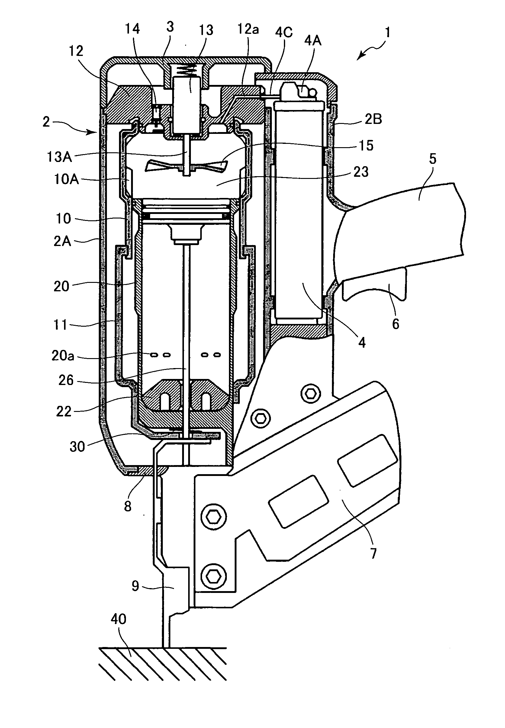
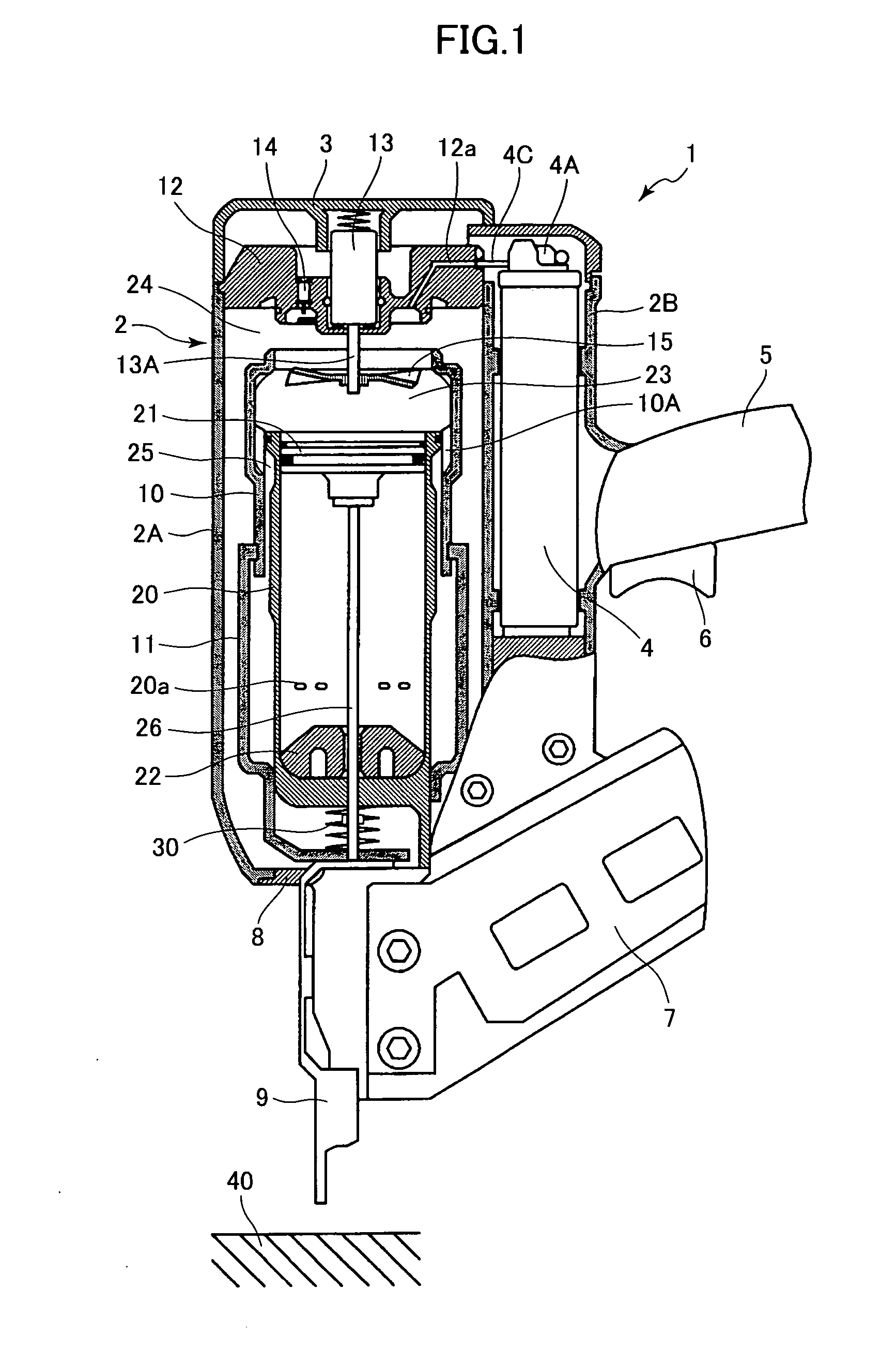
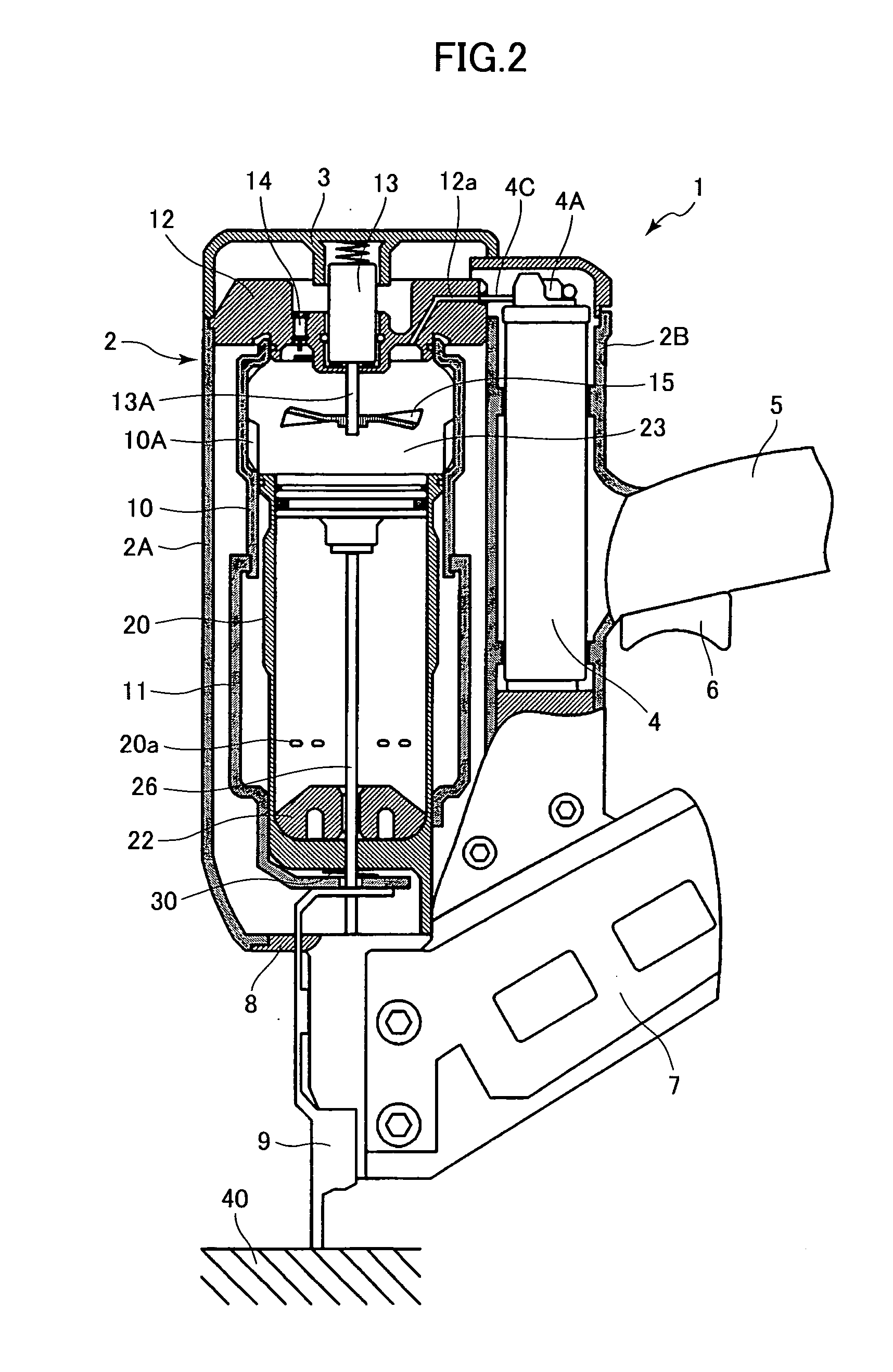
[0012] A combustion-type power tool according to one embodiment of the present invention will be described with reference to FIGS. 1 through 4. The embodiment pertains to a combustion-type nail gun. Throughout the specification, the term “upper” and “lower” are used assuming that the combustion-type nail gun is oriented in a vertical direction. The combustion-type nail gun 1 has a housing 2 constituting an outer frame and including a main housing 2A and a canister housing 2B juxtaposed thereto. The main housing 2A is formed with an exhaust port (not shown). A head cover 3 formed with an intake port (not shown) is mounted on the top of the main housing 2A. A gas canister 4 is detachably accommodated in the canister housing 2B. The gas canister 4 contains therein a combustible liquidized gas and has a gauging section 4A and an injection rod 4C extending therefrom.

[0013] A handle 5 extends from a side of the canister housing 2B. The handle 5 has a trigger switch 6 and accommodates the...


PUM


Abstract

A combustion type power tool having a combustion chamber in which a fan is rotatably provided and an ignition plug is exposed. A combustible gas and air are mixed together by the fan, and the mixture is ignited by a spark generated at the ignition plug. As a result of combustion, gas expansion occurs to permit a piston and a driver blade to move for driving a fastener into a workpiece. A spark energy is set in a range of from 0.04 J to 0.08 J.

Description

BACKGROUND OF THE INVENTION [0001] The present invention relates to a combustion-type power tool, and more particularly, to such power tool capable of driving a fastener such as a nail, an anchor, and a staple into a workpiece. [0002] In a conventional combustion-type driving tool such as a nail gun, a mixture of air and gaseous fuel injected into a combustion chamber is ignited by a spark at an ignition plug to cause gas expansion in the combustion chamber, which in turn causes a linear momentum of a piston. By the movement of the piston, a nail is driven into a workpiece. Such conventional combustion-type nail gun is described in U.S. Pat. No. 5,197,646 and Japanese Patent Publication No. H03-25307. [0003] A gas canister containing therein a combustible liquidized gas is installed in the tool. The gas canister has a gauging section for supplying a given amount of the combustible gas into the combustion chamber. However, a supply of a constant amount of the combustible gas is rathe...

Claims


Application Information

Patent Timeline
IPC IPC(8): F02B71/00F02P5/00B25C1/08F02P3/08
CPCB25C1/08F02P3/08F02D2400/06B25C1/085B25C1/18F02P15/00
Inventor NISHIKAWA, TOMOMASAFUJISAWA, HARUHISAOHTSU, SHINKI
Owner HITACHI KOKI CO LTD
Why Eureka
Try Eureka