Method for determining the temperature of an electrically heatable catalytic converter

a technology of electrical heat transfer and catalytic converter, which is applied in the direction of heat measurement, instruments, machines/engines, etc., can solve the problems of inadequate conversion of pollutants in the cold start phase, limited catalytic converter functioning, and risk of thermal damage to the catalytic converter, so as to improve the determination of the component temperature

Active Publication Date: 2019-10-31
VOLKSWAGEN AG
View PDF5 Cites 6 Cited by
  • Summary
  • Abstract
  • Description
  • Claims
  • Application Information

AI Technical Summary

Benefits of technology

[0011]The object of the invention is to further improve the determination of the component temperature of an electrically heatable catalytic converter, based on the temperature-related change in the heating resistance.
[0012]According to the invention, the object is achieved by a method for determining the temperature of an electrically heatable catalytic converter in an exhaust gas system of an internal combustion engine. The electrically heatable catalytic converter includes a heating resistor having a temperature-dependent resistance, the component temperature of the electrically heatable catalytic converter being determined from the temperature-dependent electrical resistance of the heating resistor. It is provided that the energization of the electric heating resistor takes place by closing a switch in a circuit that connects a battery of a motor vehicle to the electric heating resistor, and the component temperature is determined from the electrical resistance for a known current intensity and a known voltage. By use of a method according to the invention, determining the average component temperature of the electrically heatable exhaust gas catalytic converter, in particular an electrically heatable three-way catalytic converter or an electrically heatable four-way catalytic converter, is possible without an additional temperature sensor. The heating resistor is preferably designed as a heating disk that is mechanically connected to the catalytic converter body of the electrically heatable catalytic converter to allow the electrical energy to be efficiently introduced into the catalytic converter body. The component temperature of the electrically heatable catalytic converter is determined based on a measured value, and therefore has comparatively low susceptibility to interference from environmental influences, which in a model-based determination of the temperature can be taken into account inadequately, if at all. By use of a switchable circuit, particularly simple control of the electric heating resistance is possible, so that the heating resistor in each case is energized only briefly and thus heated, as the result of which the energy efficiency and the durability of the heating resistor and of the electrically heatable catalytic converter may be increased.
[0015]It is preferred when the energization period for the resistance measurement in such a phase is selected to be between 50 μs and 200 μs. The measurement phase should be designed to be short enough to keep the energy input into the heating resistor low. Overheating of the heating element and excessive power consumption are thus avoided. An even shorter actuation period could result in measuring errors, since for a shorter measuring period the measurement system has not yet reached its steady state. Longer measurement phases lead to unnecessarily high energy input and result in increased aging of the heating resistor.
[0016]In one advantageous embodiment of the method, it is provided that a correction factor is determined which takes into account a change in the electrical resistance of the heating resistor due to aging of the electrically heatable catalytic converter. By use of a correction factor, operation-related aging of the electrical resistance of the heating resistor may be compensated for, and the accuracy in measuring the component temperature may thus be improved over the service life of the electrically heatable catalytic converter.
[0021]In another preferred embodiment of the invention, it is provided that the resistance measurement is carried out using a four-wire measuring method. A so-called four wire measuring method is recommended if the measuring accuracy is to be further increased during the determination of the electrical resistance of the heating resistor. This does not fundamentally change the measurement and control process, but the measuring accuracy may be improved.
[0022]According to the invention, an exhaust aftertreatment system for an internal combustion engine having an exhaust gas system is proposed in which an electrically heatable catalytic converter, in particular an electrically heatable three-way catalytic converter or an electrically heatable four-way catalytic converter, is situated. The exhaust aftertreatment system includes a control unit, in particular an engine control unit of the internal combustion engine, that is configured to carry out a method according to the invention when a machine-readable program code is executed by the control unit. In an exhaust aftertreatment system according to the invention, it is possible to determine the component temperature of the electrically heatable catalytic converter accurately and in a comparatively energy-saving manner, so that the catalytic converter may be operated with high efficiency. The conversion performance of the catalytic converter may thus be increased, and / or the aging behavior of the catalytic converter may be improved.

Problems solved by technology

However, since these catalytic converters have not yet reached the temperature necessary for converting pollutants, in particular after a cold start of the internal combustion engine, conversion of the pollutants in this cold start phase is inadequate.
In general, the component temperature of the catalytic converters in the exhaust gas system of a motor vehicle is of interest, on the one hand to monitor the functioning of the catalytic converter, and on the other hand to stay within temperature limits, above which the functioning of the catalytic converter is limited and / or there is risk of thermal damage to the catalytic converter.
However, this results in a corresponding cost increase for the exhaust gas system.
In determining the component temperature based on a calculation model, due to the numerous environmental influences, uncertainties are to be expected which increase with increasing distance of the catalytic converter from the exhaust outlet of the internal combustion engine.
Therefore, for a catalytic converter in the underbody position of the motor vehicle, only inadequate modeling of the exhaust gas temperature may be possible, and the determined temperature may correspondingly differ greatly from the actual component temperature.

Method used


Image

  • Method for determining the temperature of an electrically heatable catalytic converter
  • Method for determining the temperature of an electrically heatable catalytic converter
  • Method for determining the temperature of an electrically heatable catalytic converter

Examples


Embodiment Construction

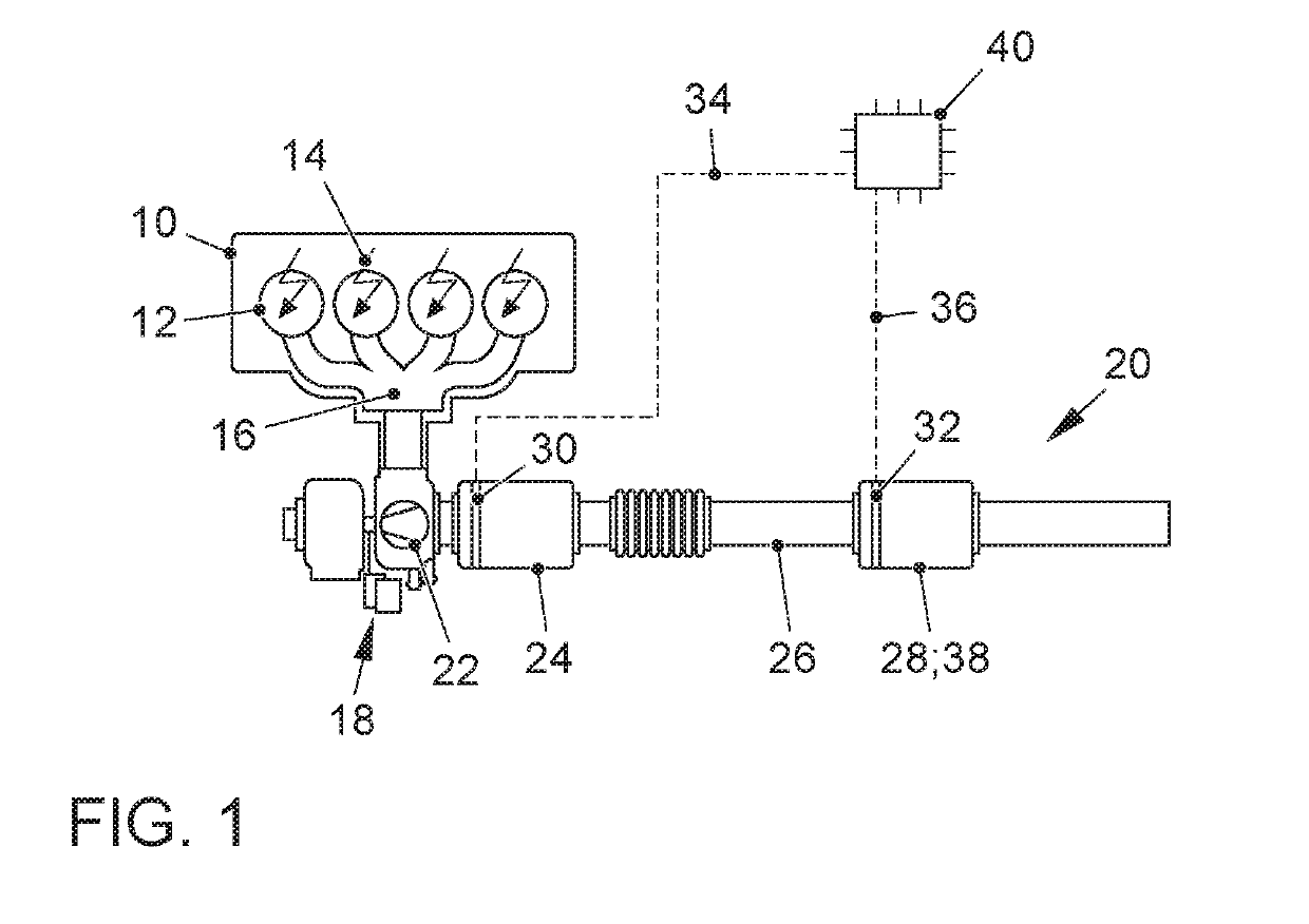
[0031]FIG. 1 shows an internal combustion engine 10, the exhaust outlet 16 of which is connected to an exhaust gas system 20. The internal combustion engine 10 is preferably designed as a spark ignition internal combustion engine 10 according to the Otto principle, and has a plurality of combustion chambers 12, on each of which at least one spark plug 14 for igniting an ignitable fuel-air mixture is situated. Alternatively, the internal combustion engine 10 may be designed as an auto-ignition internal combustion engine according to the Diesel principle. The internal combustion engine 10 is preferably designed as an internal combustion engine 10 that is supercharged by means of an exhaust gas turbocharger 18. Alternatively, the internal combustion engine 10 may be designed as a naturally aspirated engine that is not supercharged, or as an internal combustion engine 10 that is supercharged by means of a compressor or an electric compressor. The exhaust gas system 20 includes an exhaus...


PUM


Abstract

A method for determining the temperature of an electrically heatable catalytic converter having an electric heating element that includes a heating resistor, the electrical resistance of which changes as a function of the component temperature of the electrically heatable catalytic converter. This resistance is determined from the current intensity and the voltage at the electrically heatable catalytic converter, and is used to determine the component temperature of the catalytic converter, based on a characteristic curve stored in the control unit. The energization of the heating resistor for determining the component temperature takes place in each case for only a short time in order to minimize the energy input into the heating resistor and thus avoid overheating of the heating resistor. In addition, by use of the short time interval, the aim is to minimize the energy requirements for determining the component temperature of the electrically heatable catalytic converter.

Description

FIELD OF THE INVENTION[0001]The invention relates to a method for determining the temperature of an electrically heatable catalytic converter in an exhaust gas system of an internal combustion engine, and an exhaust gas system having such an electrically heatable catalytic converter.BACKGROUND OF THE INVENTION[0002]In internal combustion engines, the exhaust aftertreatment of the combustion gases takes place by means of catalytic converters situated in the exhaust gas system of the internal combustion engine. However, since these catalytic converters have not yet reached the temperature necessary for converting pollutants, in particular after a cold start of the internal combustion engine, conversion of the pollutants in this cold start phase is inadequate. Electrically heatable catalytic converters are known from the prior art, in which the catalytic converter may be heated by an electric heating element, independently of the exhaust gas flow. The period of time in which the cataly...

Claims


Application Information

Patent Timeline
Patent Type & Authority Applications(United States)
IPC IPC(8): F01N3/20F01N11/00
CPCF01N11/005F01N2900/1602F01N3/2026F01N11/002F01N9/00F01N3/2013H02M3/156G01K7/16G01R27/02F01N2240/16F01N2390/02F01N2560/12F01N2900/0602F01N2900/1626F01N2900/0601Y02T10/12Y02T10/40
Inventor NAUMANN, HARDYPAUKNER, STEFAN
Owner VOLKSWAGEN AG
Why Eureka
Try Eureka