Fracture resistant friction stir welding tools

Inactive Publication Date: 2006-03-02
ARCONIC INC
View PDF13 Cites 59 Cited by
  • Summary
  • Abstract
  • Description
  • Claims
  • Application Information

AI Technical Summary

Benefits of technology

[0009] The present invention is a friction stir welding tool including an integral pin and shoulder, a pin portion of the integral pin and shoulder being for plunging into one or more workpiece(s) to perform a friction stir welding operation on the workpiece(s). The shoulder portion of the tool includes a working surface for engaging at least one surface of the workpieces(s) to prevent plasticized material from flowing out of the workpiece(s). A proximal end of the pin portion is contiguous with the working surface of the shoulder portion of the integral pin and shoulder. The friction stir welding tool further includes a tool body defining a cavity therein, said cavity for receiving at least a portion of the shoulder portion of the integral pin and shoulder, the tool body further including a shank for engagement with a chuck or collet of a friction stir welding machine. The friction stir welding tool further includes a tension member disposed at least partially within the pin portion of the

Problems solved by technology

However, such materials are generally subject to failure by fracture.
Tool failure thus puts limitations on the materials which can be welded by f

Method used


Image

  • Fracture resistant friction stir welding tools
  • Fracture resistant friction stir welding tools
  • Fracture resistant friction stir welding tools

Examples


Embodiment Construction

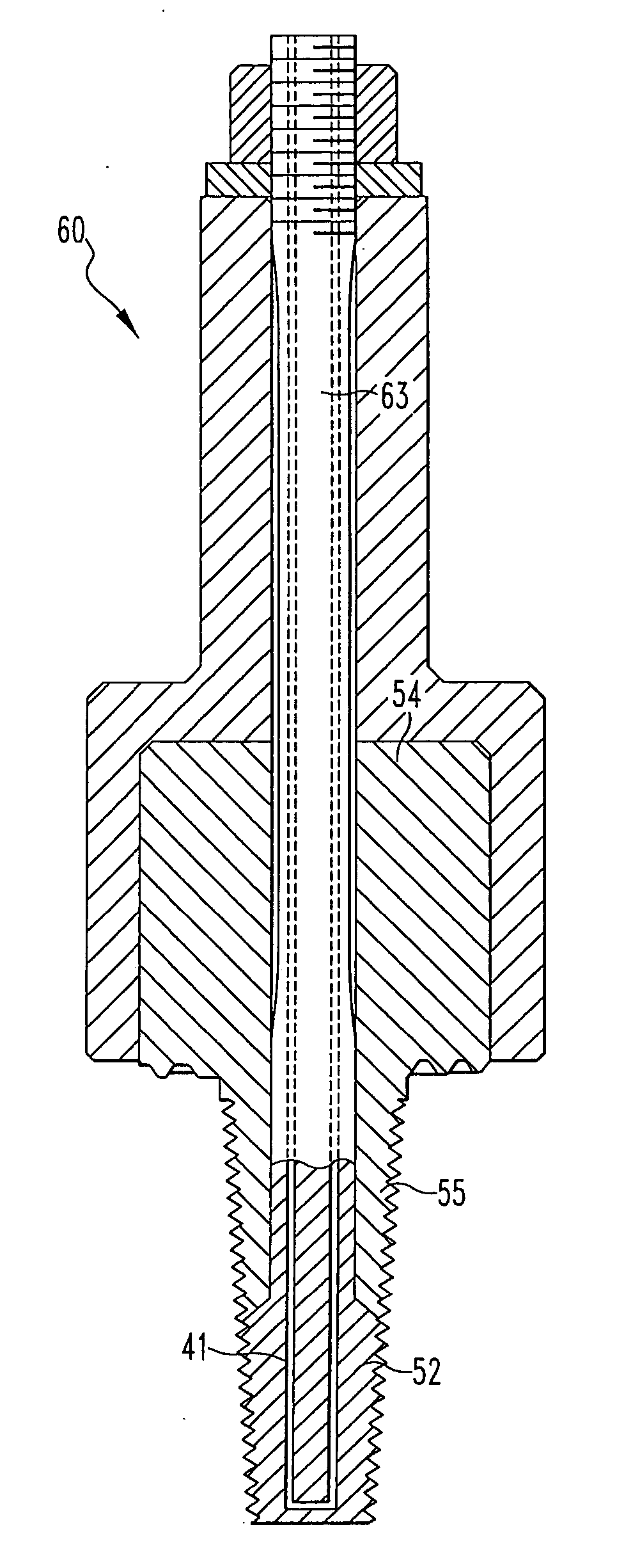
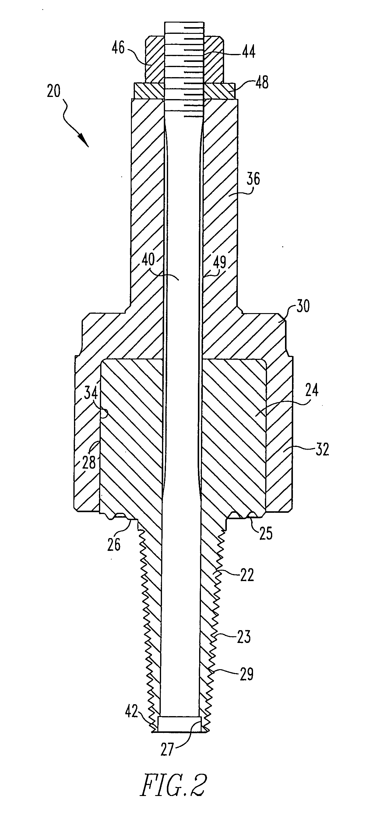
[0018] Attention is directed to FIG. 2, which is an illustration of a friction stir welding tool 20 according to one embodiment of the present invention. Friction stir welding tool 20 includes a pin 22 which is integral with a shoulder 24. Pin 22 has working surface 29, preferably with threads 23. Shoulder 24 has working surface 26, preferably with spiral threads 25. Friction stir welding tool 20 includes a tool body 30 with a compression sleeve 32 defining therewithin a cavity 34.

[0019] Compression sleeve 32 provides inward compression on outer surface 28 of shoulder 24. Tool body 30 further includes a shank 36 which is for engagement with a chuck or collet (not shown) of a friction stir welding machine (not shown), to be rotated thereby. Preferably, when friction stir welding tool 20 is rotated in the direction such that threads 23 on pin 22 push plasticized material downwardly along pin 22, into a joint being welded, the spiral threads 25 urge plasticized material inwardly, towa...


PUM

PropertyMeasurementUnit
Angleaaaaaaaaaa
Forceaaaaaaaaaa
Angleaaaaaaaaaa

Abstract

A fracture resistant friction stir welding tool includes a pin for plunging into one or more workpiece(s) to be welded and a shoulder for preventing plasticized material from flowing out of the joint being welded. The friction stir welding tool includes a tool body including a cavity for receiving the shoulder and exerting a compressive stress on the shoulder, and the pin is placed in compression by an axial tension member in the pin.

Description

CROSS REFERENCE TO RELATED APPLICATIONS [0001] The present invention is based on the provisional patent application entitled “Advanced Friction Stir Welding Tools”, Application No. 60 / 605,960, filed on Aug. 30, 2004. The present invention is also closely related to the regular patent application entitled “Advanced Friction Stir Welding Tools”, U.S. Ser. No. 11 / 100,878, filed on Apr. 7, 2005. Furthermore, the teachings of both the provisional application and the regular application are hereby incorporated herein by reference thereto.FIELD OF THE INVENTION [0002] The present invention relates to friction stir welding tools and, more particularly, the present invention relates to friction stir welding tools having fracture resistant features. BACKGROUND OF THE INVENTION [0003] The Friction Stir Welding (FSW) process is a solid-state based joining process, which makes it possible to weld a wide variety of materials (Aluminum, Copper, Stainless Steels, etc.) to themselves and to weld var...

Claims


Application Information

Patent Timeline
IPC IPC(8): B23K20/12
CPCB23K20/1255
Inventor STOL, ISRAELCOBES, JOHN W.
Owner ARCONIC INC
Why Eureka
Try Eureka