
Pneumatic suspension system for a vehicle

Inactive Publication Date: 2006-03-02
WABCO GMBH
View PDF20 Cites 23 Cited by
  • Summary
  • Abstract
  • Description
  • Claims
  • Application Information

AI Technical Summary

Benefits of technology

[0006] One advantage of the present invention is that it is possible to prevent unwanted changes in level of the vehicle body in the “wrong” direction, such changes being considered to be disruptive and resulting in a visual impression that is not acceptable.
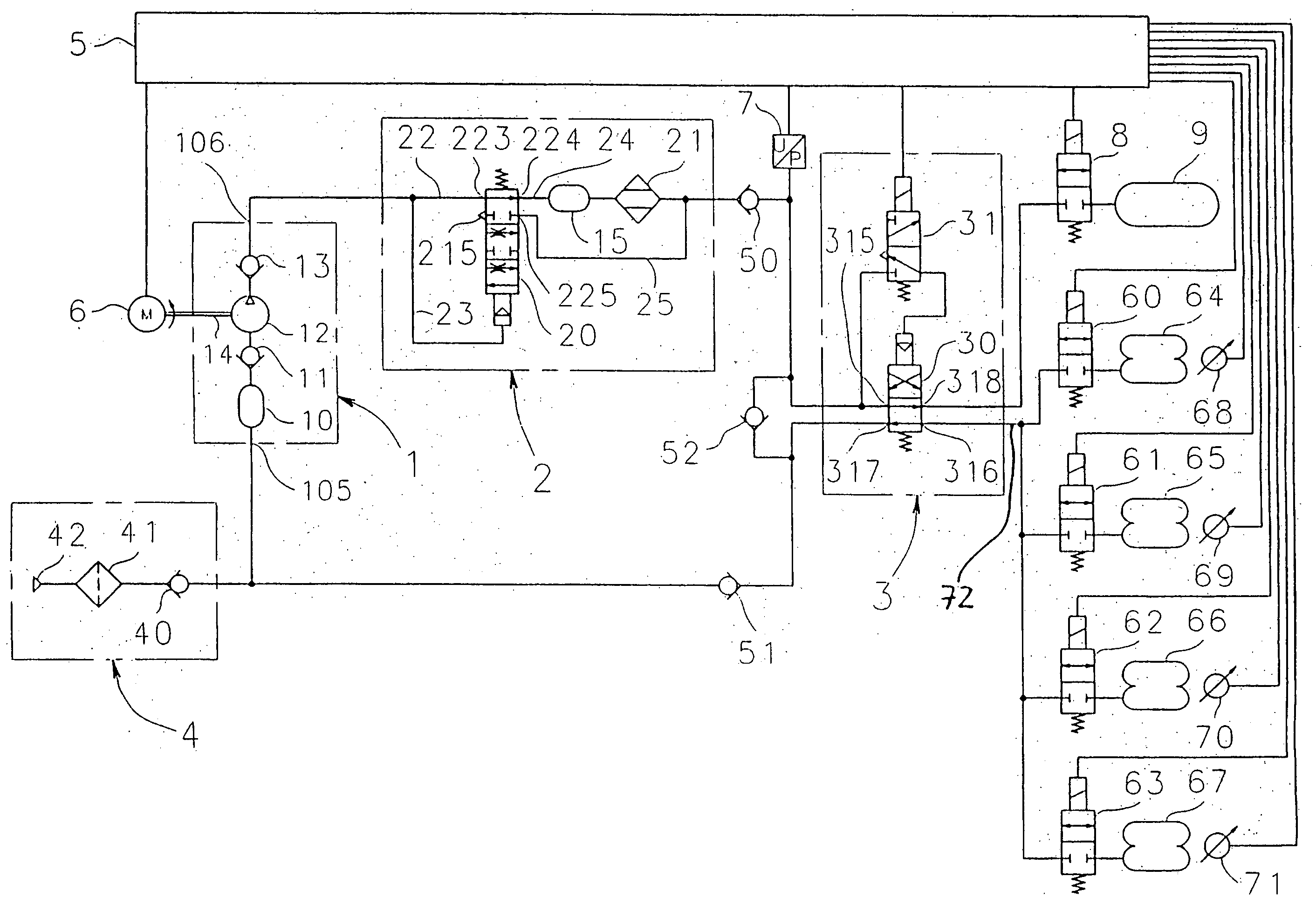
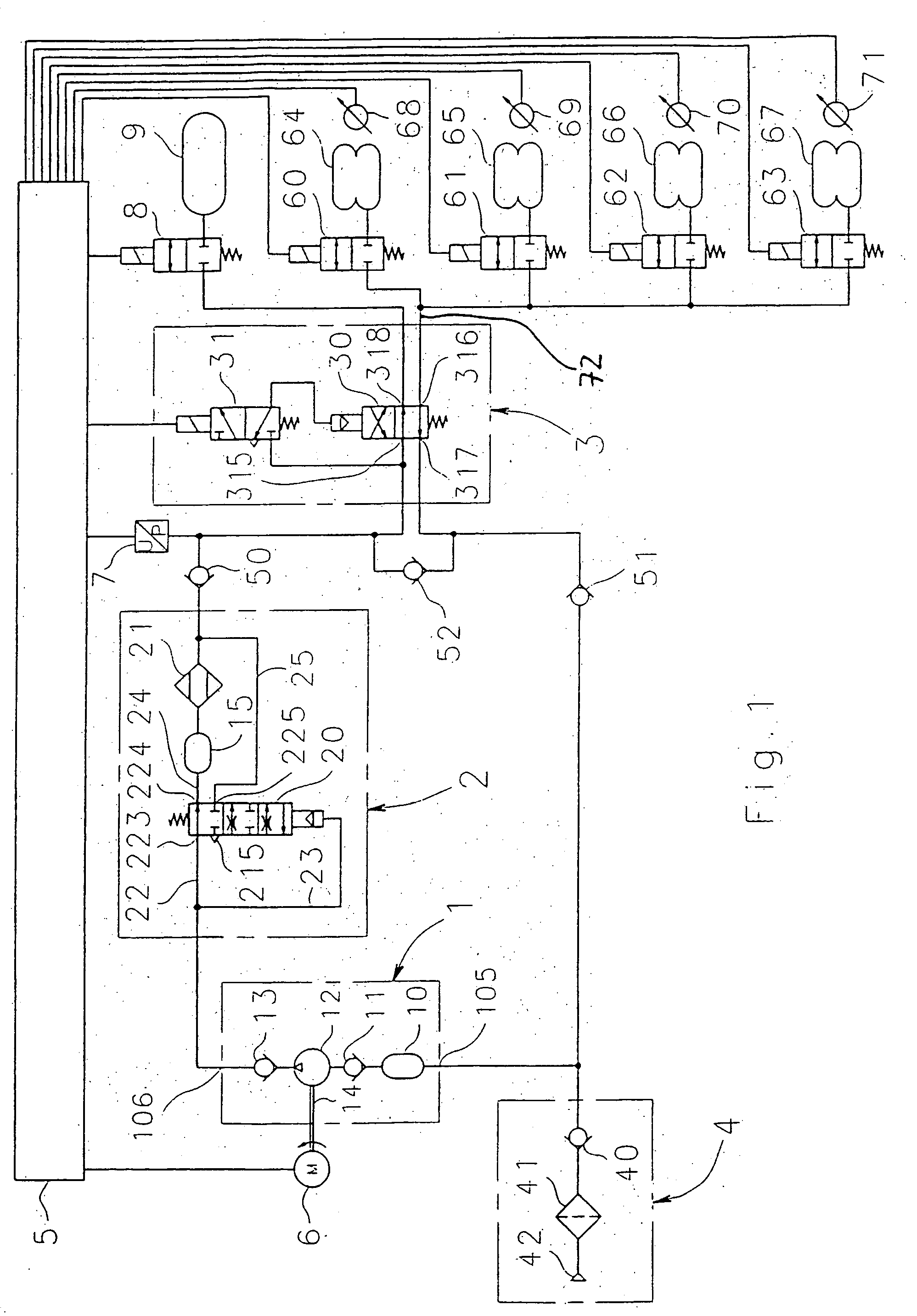
[0007] The present invention has the further advantage that it can be implemented very cost-effectively by the selective use of one or two check valves, since check valves are of relatively simple construction and are therefore inexpensive. Depending on need, that is, on the volumes present in the air-suspension system, a check valve can be disposed on the inlet side of the compressed-air delivery device and / or on the outlet side of the compressed-air delivery device or on the outlet side of an air-discharge / dryer device mounted downstream from the compressed-air delivery device. The advantageous use of two check valves will be described in greater detail hereinafter in connection with practical examples.
[0008] A further advantage of the present invention is that it can be used in a large number of different versions of the air-suspension system, as will be described in greater detail hereinafter in connection with practical examples.
[0009] According to one embodiment of the present invention, the compressed air flows through the air-discharge / dryer device in the same direction in all operating conditions of the air-suspension system. This has the advantage that, because of the uniform flow direction, one check valve can be disposed between the air-discharge / dryer device and the valve arrangement. As a result, the volume of the air dryer, especially of the air-dryer cartridge, is also isolated by the check valve from the air-suspension bellows.
[0010] Still other objects and advantages of the present invention will in part be obvious and will in part be apparent from the specification.
[0011] The present invention accordingly comprises the features of construction, combination of elements, and arrangement of parts which will be exemplified in the construction hereinafter set forth, and the scope of the invention will be indicated in the claims.

Problems solved by technology

This leads, at first, to an undesired increase of the compressed-air quantity in the air-suspension bellows.
Depending on the size of the volumes present in further components of the air-suspension system, such behavior may prove to be disruptive for the function of the air-suspension system, since changes in the compressed-air quantity in the air-suspension bellows lead to changes in the level height of the vehicle body.

Method used


Image

  • Pneumatic suspension system for a vehicle
  • Pneumatic suspension system for a vehicle
  • Pneumatic suspension system for a vehicle

Examples


Embodiment Construction

[0022] The function of an air-suspension system for a vehicle is to adjust and control, via leveling means, the level height of the vehicle body relative to the vehicle axles and thus indirectly relative to the roadway. For this purpose such a leveling means is preferably disposed on each wheel of a vehicle, and air-suspension bellows are preferably used as leveling means. By filling or venting the individual air-suspension bellows, any desired level heights of the vehicle body can be adjusted within an adjustment range provided for the purpose. Such air-suspension systems are preferably operated with compressed air as the pressurized medium.

[0023] In air-suspension systems constructed and arranged as open systems, compressed air is sucked in as necessary from the surroundings, or in other words from the atmosphere, and pumped into the air-suspension bellows or into a compressed-air accumulator, or in other words a reservoir tank. The compressed-air accumulator, however, is not abs...


PUM


Abstract

A pneumatic suspension system for a vehicle includes pneumatic bellows connectable by means of a valve arrangement to at least one other component of the pneumatic suspension system in order to selectively increase or decrease the amount of compressed air therein. The other component contains at least one volume. Undesirable changes in the amount of compressed air inside the pneumatic bellows arising as a result of pressure compensation are avoided or reduced to a non-disruptive level a return valve between the valve arrangement and the volume which prevents compressed air from flowing between the pneumatic bellows and the volume in one direction of flow.

Description

BACKGROUND OF THE INVENTION [0001] The present invention relates to an air-suspension system for a vehicle, especially a closed or partly closed system. [0002] An air-suspension system of the general type under consideration is described in DE 199 59 556 C1. [0003] In such conventional air-suspension systems there is provided at least one air-suspension bellows which, via a valve arrangement, can be placed in communication with at least one further component of the air-suspension system in order to selectively increase or decrease the compressed-air quantity contained therein. In the known air-suspension system described in DE 199 59 556 C1, a compressed-air delivery device such as a compressor is used as such a further component, which serves, on the one hand, to pump air as needed from a compressed-air accumulator into the air-suspension bellows, and, on the other hand, to pump air as needed from the air-suspension bellows back into the compressed-air accumulator. To establish the...

Claims


Application Information

Patent Timeline
IPC IPC(8): B60G11/26B60G17/015B60G17/04B60G17/052
CPCB60G17/0155B60G2500/2014B60G17/0523
Inventor GEIGER, HARTMUT
Owner WABCO GMBH
Learn More