Vertical outrigger leg

a technology of vertical outrigger and work machine, which is applied in the direction of soil shifting machine/dredger, vehicle maintenance, transportation and packaging, etc., can solve the problems of limited height of outriggers at their furthest point from the chassis, unique design of outrigger assembly, and limited height of outriggers. , to achieve the effect of increasing vertical lift, facilitating operation, and facilitating maintenan

Inactive Publication Date: 2006-03-02
PUTZMEISTER AG
View PDF29 Cites 22 Cited by
  • Summary
  • Abstract
  • Description
  • Claims
  • Application Information

AI Technical Summary

Benefits of technology

[0012] In a preferred embodiment of the invention, the inner housing extends from the mobile work machine until the proper extended width is achieved. Both the hydraulic cylinder and the leg member may be extended vertically by use of hydraulic pressure to a ground-engaging position with the support pad mounted at the lower end of the leg member contacting the ground. Further extension of the hydraulic cylinder and the leg member results in the lifting of the vehicle body off the ground to further stabilize the machine during operation. An advantage of the outrigger assembly of the present invention is that it affords greater stabilization for the mobile work machine because of the expanded outrigger leg horizontal reach positions, and increased vertical lift whereby the mobile work machine may be stabilized more effectively in a greater range of ground types and slopes.

Problems solved by technology

This often requires placement and operation of the vehicle on rough and uneven ground.
A vehicle-mounted conveyor system presents unique problems in the design of the outrigger assembly.
However, due to the length of the extendable boom contained on the discharge conveyor, a significant amount of weight positioned away from the center of gravity of the vehicle must be supported by the vehicle chassis.
The combination of these two requirements dictates that the height the outriggers at their furthest point from the chassis will be limited.
Because of this height limit, a single-stage vertical leg will be very limited in its capability to elevate the entire machine into a stable condition.
Additionally, uneven terrain on the job site prevents a stable set up unless the vertical legs were of a telescoping design of multiple cylinders used to drive the multiple leg sections.

Method used


Image

  • Vertical outrigger leg
  • Vertical outrigger leg
  • Vertical outrigger leg

Examples


Embodiment Construction

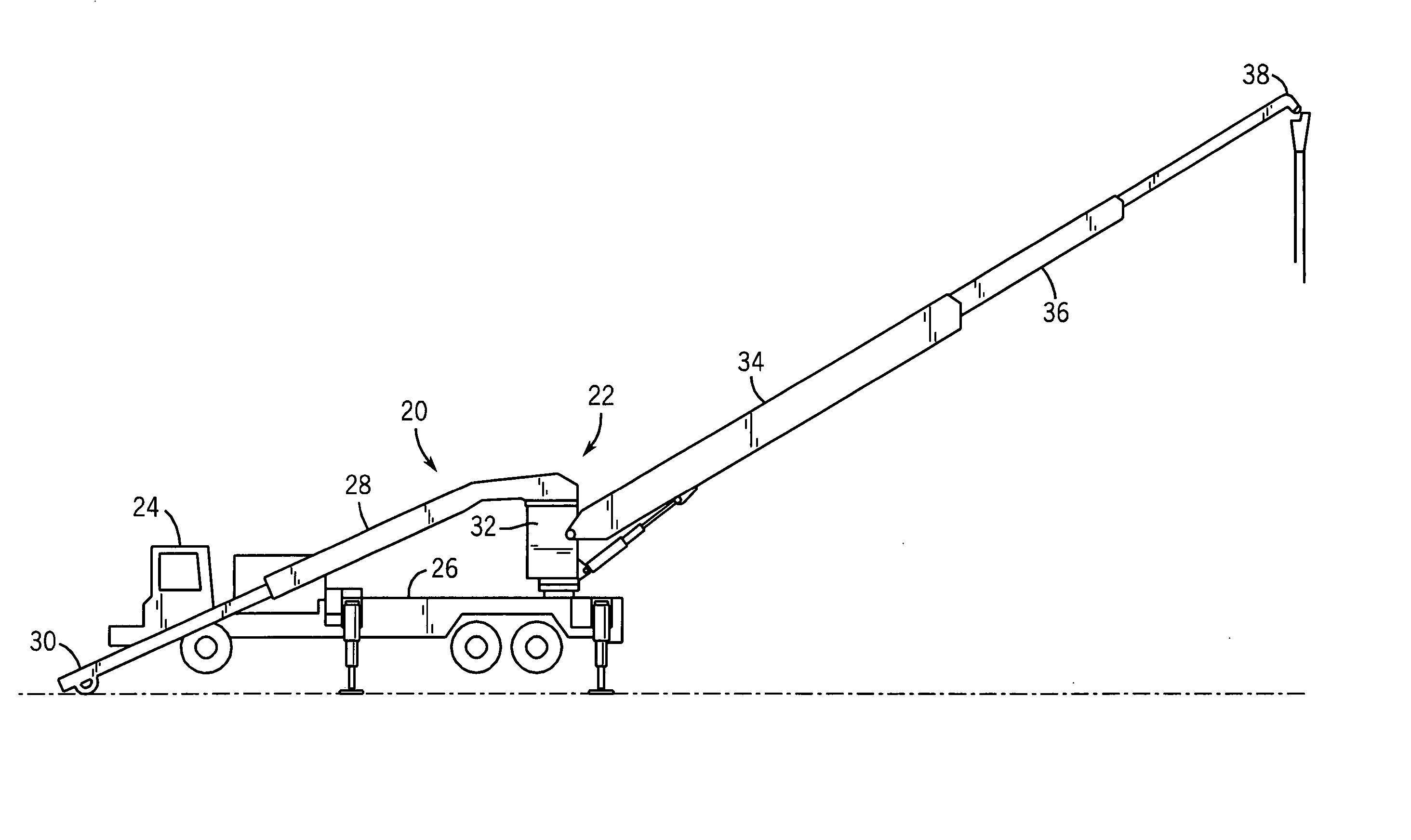
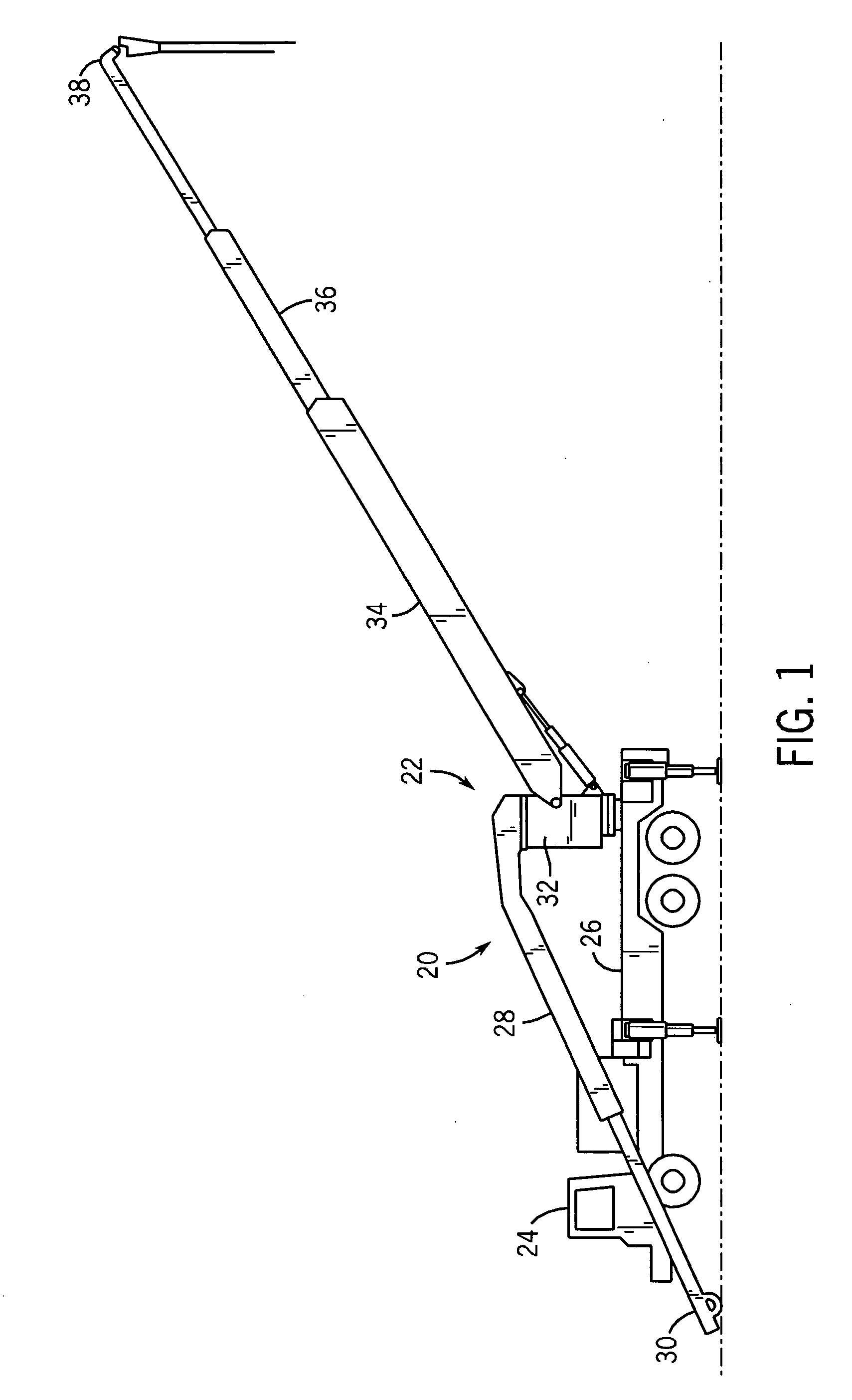
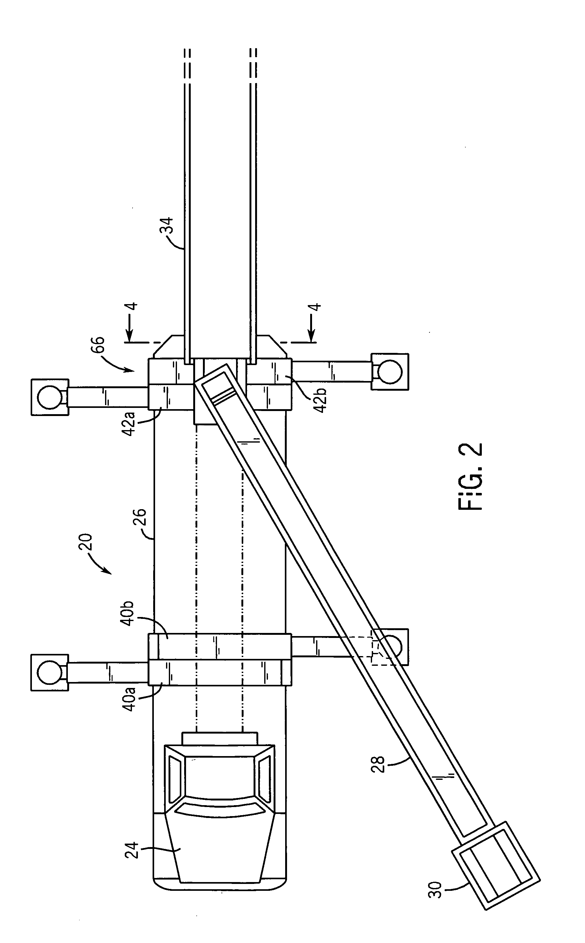
[0024] A mobile work machine, such as a self-propelled vehicle 20 including a vehicle-mounted conveyor system 22 for transporting an aggregate material such as concrete is best shown in FIGS. 1 and 2. The vehicle 20 includes a conventional cab 24 and a torque tube 26. The vehicle 20 is of a size such that it does not exceed the legal dimensional limits for over the highway travel.

[0025] The conveyor system 22 includes an in-feed conveyor assembly 28 that receives the supply of aggregate material, such as concrete, from a supply source 30 and transports the material upward along a moving in-feed conveyor belt. The in-feed conveyor assembly 28 is rotatable about the vehicle 20 such that the in-feed conveyor assembly 28 can receive the supply of material at various locations around the vehicle 20.

[0026] The conveyor system 22 includes a main turret 32 that is rotatably mounted to the torque tube 26 of the vehicle 20. A discharge conveyor assembly 34 is pivotally mounted to the main t...


PUM


Abstract

An outrigger assembly for the support and stabilization of a mobile work machine, such as a vehicle-mounted telescopic belt conveyor, while the machine is operating. The outrigger assembly includes a vertical outrigger leg assembly. The vertical outrigger leg assembly is attached to the end of a horizontally extending member and includes multiple telescopically extendable sections that extend until a support pad is in contact with the work surface, then raise the mobile work machine off of the ground into a stabilized position. The multiple leg sections allow for increased vertical lifting distance, thus improving stability on uneven work surfaces, and allow the outrigger assembly to be used on larger machines.

Description

BACKGROUND OF THE INVENTION [0001] The present invention relates to an outrigger assembly for stabilizing a mobile work machine. More specifically, the present invention is an outrigger assembly for stabilizing a self-propelled, vehicle-mounted conveyor system used to place concrete or other materials in a desired location where the vertical movement of the outrigger leg is actuated by utilizing multiple cylinders to direct the multiple telescoping leg sections. [0002] Vehicle-mounted, extendable material placement systems have been in use for some time and are the subject of numerous prior patents. In such vehicles, a telescopic or sectional-unfolding boom extends from a rotating turret attached to the vehicle. The substantial amount of weight extending from the vehicle chassis necessitates the use of outriggers to stabilize the vehicle and prevent the vehicle from tilting or overturning. Extendable material placement systems are most typically utilized during the construction of n...

Claims


Application Information

Patent Timeline
Patent Type & Authority Applications(United States)
IPC IPC(8): E02F3/00
CPCE02F9/085B66C23/80
Inventor MAYER, MARTIN G.
Owner PUTZMEISTER AG
Why Eureka
Try Eureka