Ejection head and image forming apparatus

a technology of image forming apparatus and ejection head, which is applied in the direction of printing and inking apparatus, etc., can solve the problems of electrostrictive thin plates, dimensional restrictions, and even more severe restrictions on the structure and shape of actuators, so as to increase the displacement volume of the pressure chamber, suppress the effect of pressure reduction and increase the displacement of the diaphragm

Inactive Publication Date: 2006-03-02
FUJIFILM CORP
View PDF12 Cites 8 Cited by
  • Summary
  • Abstract
  • Description
  • Claims
  • Application Information

AI Technical Summary

Benefits of technology

[0021] The present invention is contrived in view of such circumstances, and an object thereof is to provide an ejection head and an image forming apparatus that can achieve satisfactory ejection even when using a high-viscosity liquid, without causing the ejection efficiency to decline, whereby can achieve higher density.

Problems solved by technology

However, in a print head formed to a high density, the structure and shape of the actuators and pressure chambers are subject to dimensional restrictions, and these restrictions are even more severe in the case of a print head formed to particularly high density.
In addition, an electrostrictive thin plate disclosed in Japanese Patent Application Publication No. 5-246024 is difficult to manufacture.
However, it is doubtful whether ejection characteristics can be made more efficient.
In the inkjet-type print head and piezoelectric converter disclosed in Japanese Patent Application Publication No. 2003-25573, the object thereof is to suppress variation in the manufacture and assembly of piezoelectric converters, but there is no disclosure of technology for improving ejection characteristics.
In the liquid droplet ejection head, ink cartridge and inkjet recording apparatus disclosed in Japanese Patent Application Publication No. 2004-66652, when manufacturing the diaphragm having a hinge structure, the manufacturing process increases in complexity.
However, it is doubtful whether satisfactory displacement could be obtained when the viscosity (or other properties) of the ink to be ejected is changed.

Method used


Image

  • Ejection head and image forming apparatus
  • Ejection head and image forming apparatus
  • Ejection head and image forming apparatus

Examples


Embodiment Construction

General Composition of Inkjet Recording Apparatus Including Pint Head

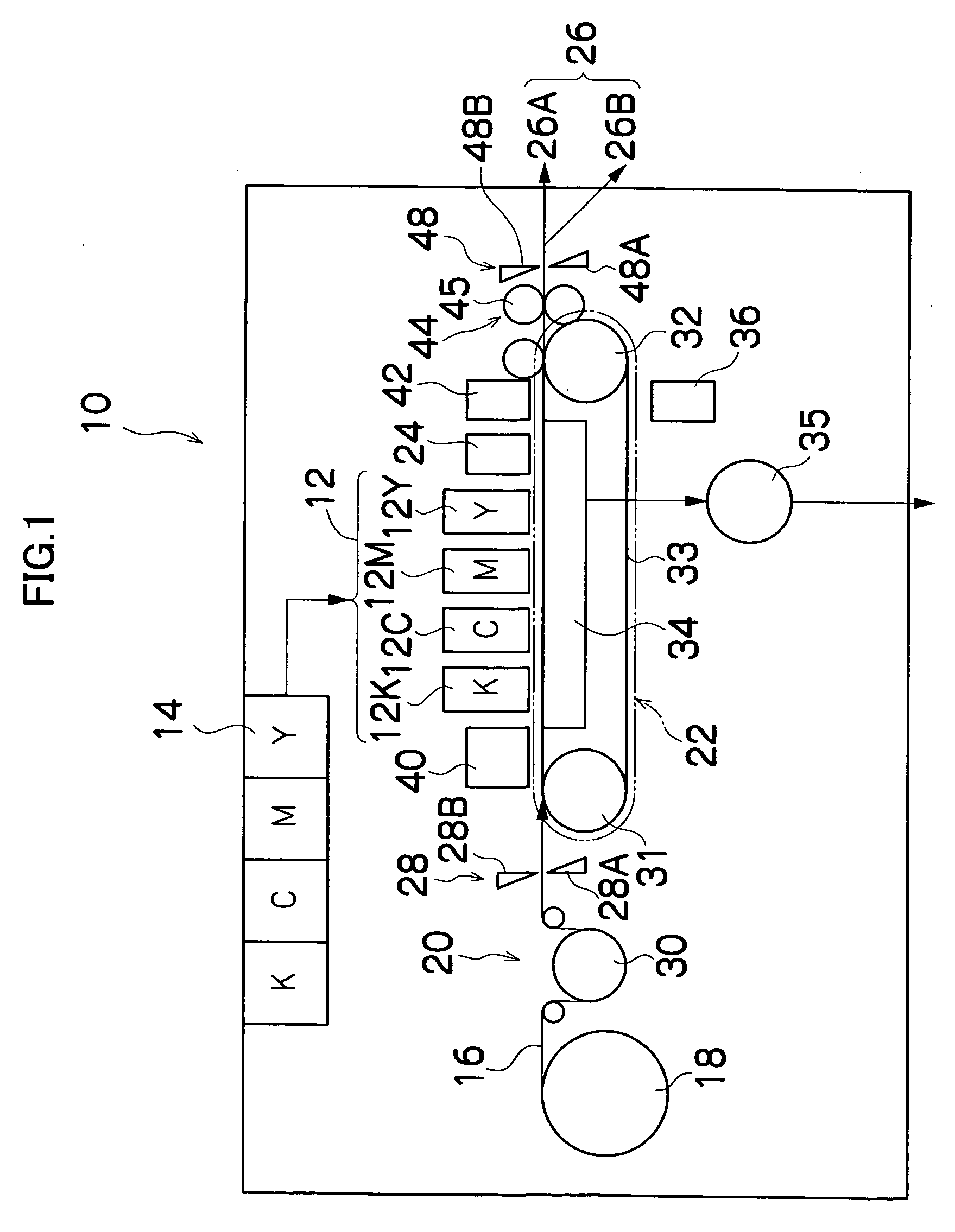
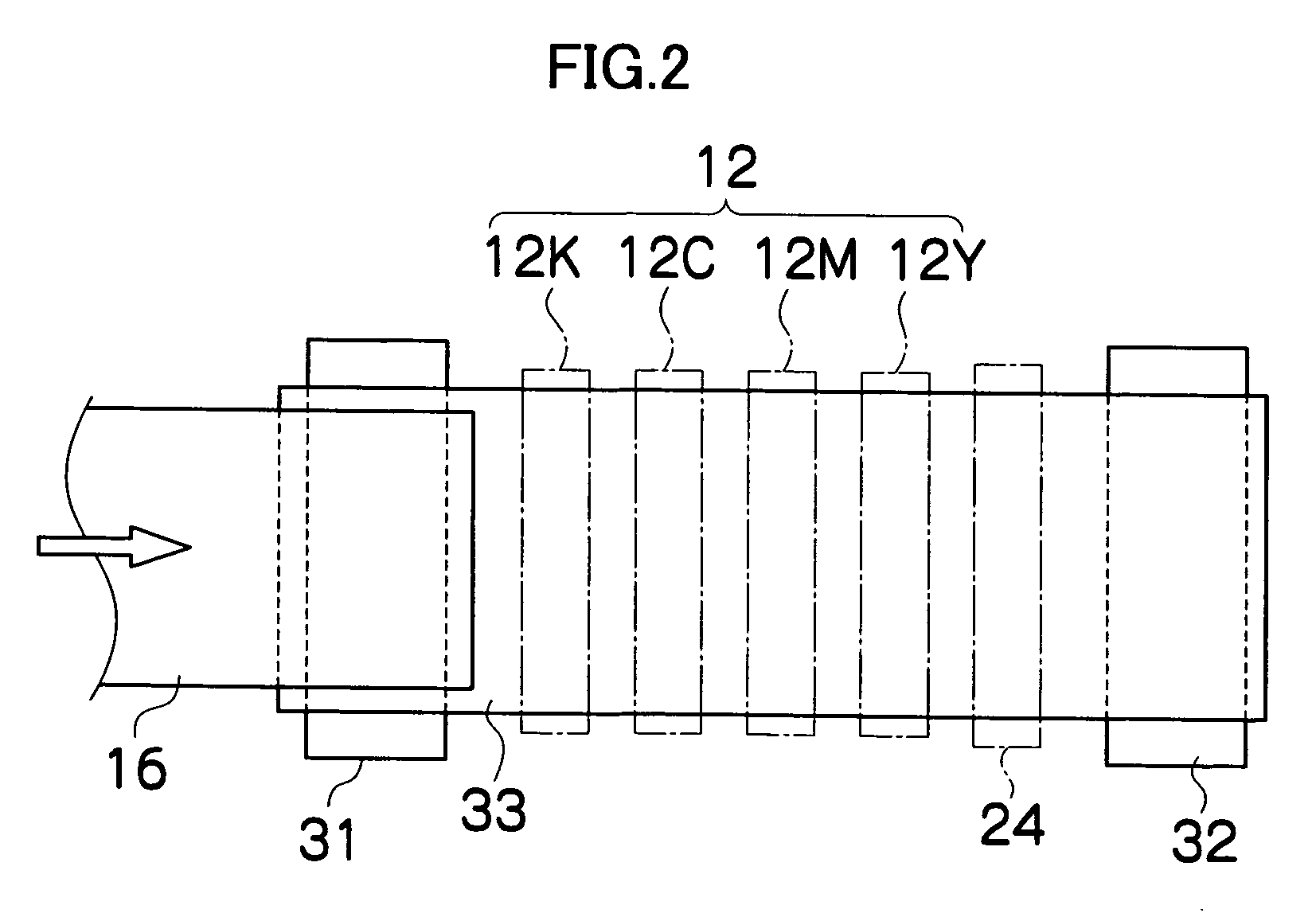
[0061]FIG. 1 is general schematic drawing of an inkjet recording apparatus including a print head according to an embodiment of the present invention. As shown in FIG. 1, the inkjet recording apparatus 10 comprises: a printing unit 12 having a plurality of print heads 12K, 12C, 12M, and 12Y for ink colors of black (K), cyan (C), magenta (M), and yellow (Y), respectively; an ink storing and loading unit 14 for storing inks of K, C, M and Y to be supplied to the print heads 12K, 12C, 12M, and 12Y; a paper supply unit 18 for supplying recording paper 16; a decurling unit 20 for removing curl in the recording paper 16 supplied from the paper supply unit 18; a suction belt conveyance unit 22 disposed facing the nozzle face (ink-droplet ejection face) of the printing unit 12, for conveying the recording paper 16 while keeping the recording paper 16 flat; a print determination unit 24 for reading the printed result prod...


PUM


Abstract

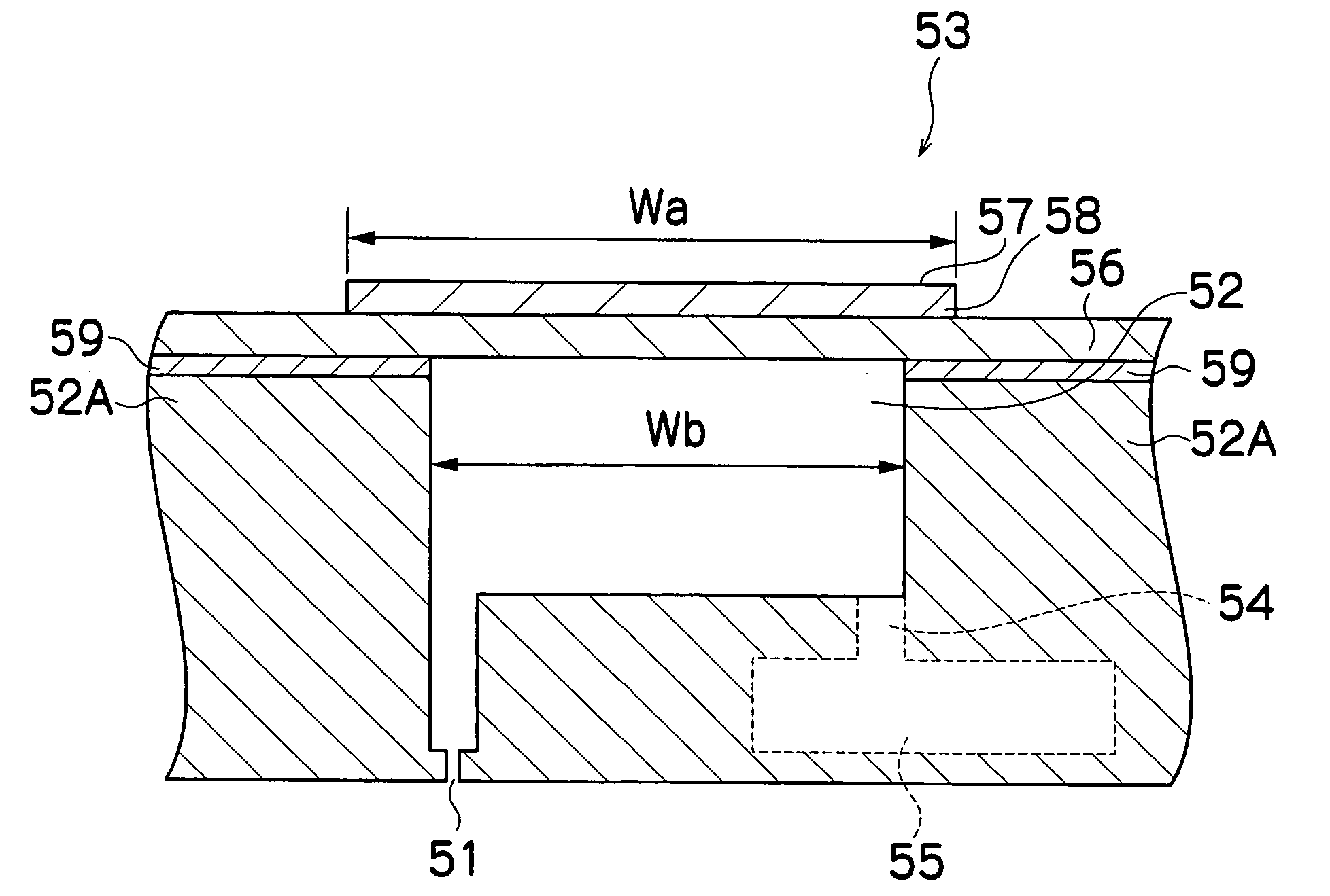
The ejection head comprises: a wall member which forms a pressure chamber and has an ejection aperture through which droplets of a liquid are ejected onto an ejection receiving medium, the pressure chamber accommodating the liquid to be ejected from the ejection aperture; a diaphragm which causes a volume of the pressure chamber to change by performing bending deformation so as to cause the liquid accommodated in the pressure chamber to be ejected from the ejection aperture, the diaphragm forming one face of the pressure chamber; a piezoelectric element which causes the diaphragm to perform bending deformation in accordance with a drive signal, the piezoelectric element being disposed on the diaphragm; and a bonding member which bonds the diaphragm with the wall member, wherein the bonding member comprises a low-rigidity member; and the piezoelectric element has a greater length than an internal effective length of the pressure chamber.

Description

BACKGROUND OF THE INVENTION [0001] 1. Field of the Invention [0002] The present invention relates to an ejection head and an image forming apparatus, and more particularly to a structure of an ejection head which ejects a liquid onto an ejection receiving medium. [0003] 2. Description of the Related Art [0004] In recent years, inkjet printers have come to be used widely as data output apparatuses for outputting images, documents, or the like. By driving recording elements, such as nozzles provided in a recording head, in accordance with data, an inkjet printer is able to form data onto a recording medium such as recording paper, by means of ink ejected from the nozzles. [0005] In an inkjet printer, a desired image is formed on a recording medium by causing a print head having a plurality of nozzles and a recording medium to move relatively to each other, while causing ink droplets to be ejected from the nozzles. [0006] The method for causing the ink to be ejected from the print head...

Claims


Application Information

Patent Timeline
Patent Type & Authority Applications(United States)
IPC IPC(8): B41J2/045
CPCB41J2/14233B41J2/161B41J2202/21B41J2002/14459B41J2202/20B41J2/1623
Inventor MITA, TSUYOSHI
Owner FUJIFILM CORP
Why Eureka
Try Eureka