System and method for increasing fuel economy of a vehicle including a SCR catalyst

A technology of SCR catalytic converter and exhaust system, which is applied in the direction of charging system, combustion engine, machine/engine, etc., and can solve the problems of engine fuel economy lower than expected, engine fuel economy reduction, etc.

Active Publication Date: 2013-10-23
FORD GLOBAL TECH LLC
View PDF7 Cites 3 Cited by
  • Summary
  • Abstract
  • Description
  • Claims
  • Application Information

AI Technical Summary

Problems solved by technology

However, the engine's fuel economy can be slightly reduced when EGR is increased
As a result, engine fuel economy can be lower than expected

Method used


Image

  • System and method for increasing fuel economy of a vehicle including a SCR catalyst
  • System and method for increasing fuel economy of a vehicle including a SCR catalyst
  • System and method for increasing fuel economy of a vehicle including a SCR catalyst

Examples


Embodiment Construction

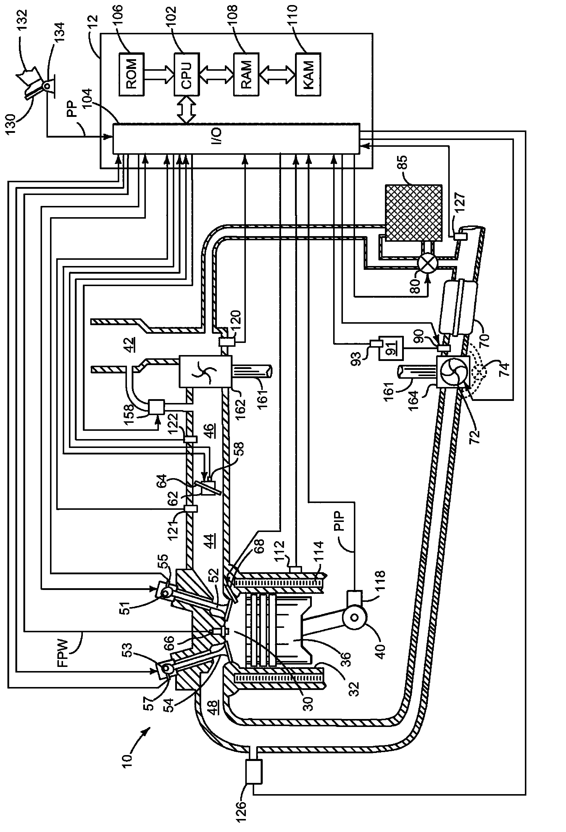
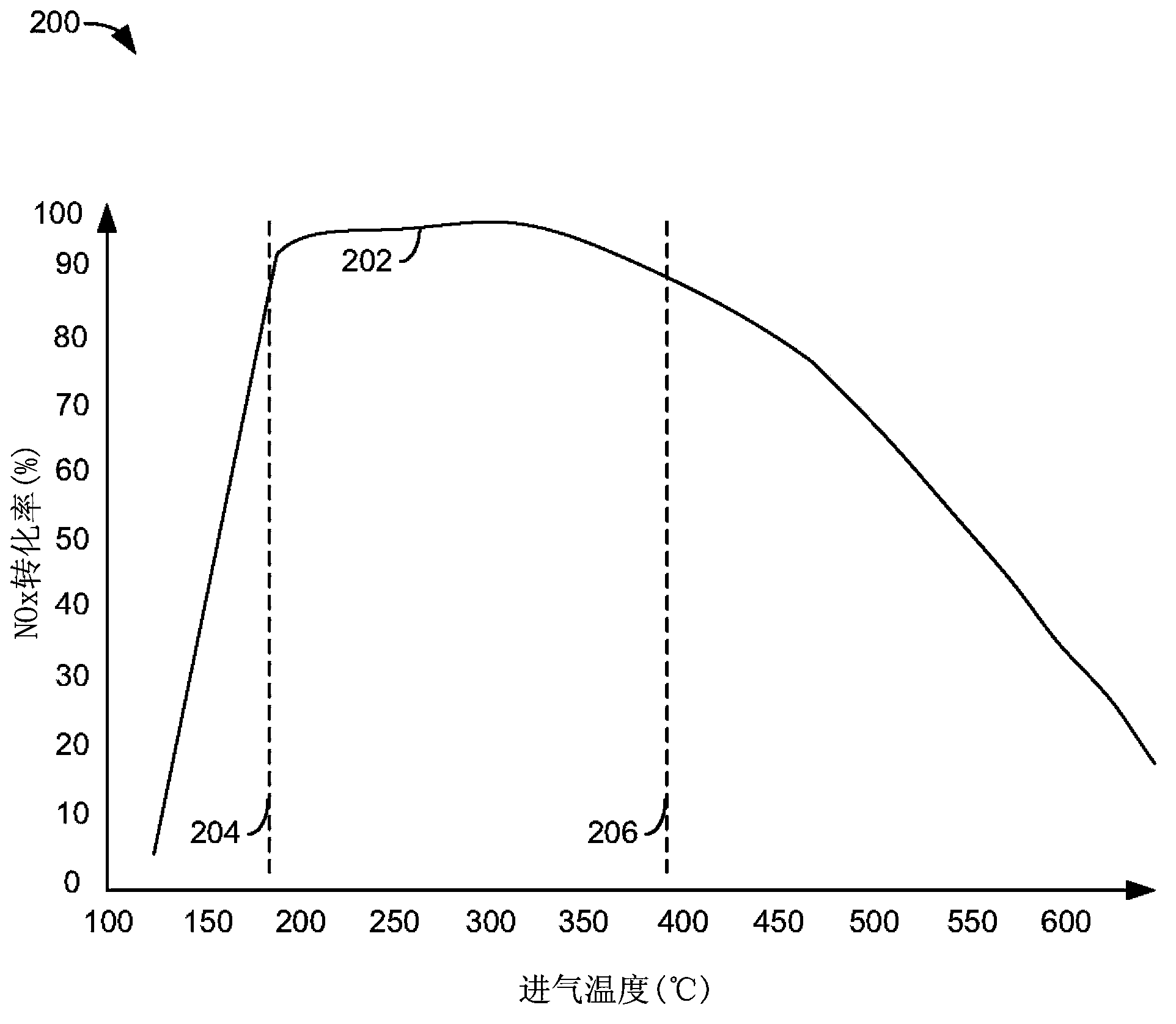
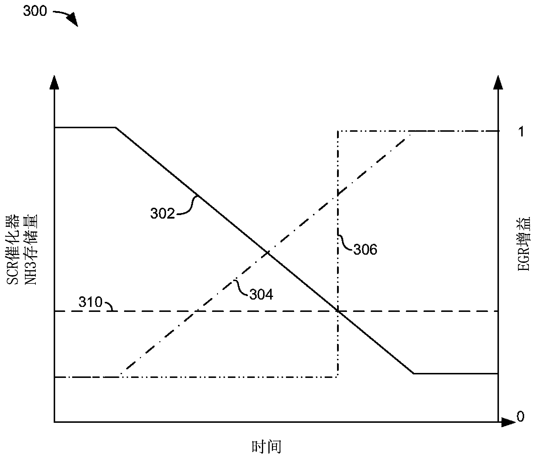
[0024] The present invention relates to improving the fuel economy of vehicles having SCR catalysts. figure 1 An example of a supercharged diesel engine is shown, where when the SCR catalyst is operating in the high-efficiency operating region, Figure 5 The method can adjust the engine operating conditions, thereby reducing fuel consumption. figure 2 An exemplary SCR catalyst conversion efficiency map is shown that identifies a temperature range during engine operation that may reduce engine fuel consumption. image 3 Shown to respond to SCR NH 3 An instance of the manner in which EGR is adjusted is stored. In some instances, the flow of urea to the exhaust system is restricted, thereby reducing Figure 4 Possibility of deposit formation as shown in . Figure 5 A method for reducing engine fuel consumption of an engine including an SCR catalyst is provided. At last, Image 6 shown in which can be applied Figure 5 An exemplary vehicle of the method.

[0025] refer to...


PUM


Abstract

Methods and systems for increasing fuel economy of a vehicle including a SCR catalyst are presented. In one example, an amount of EGR provided to an engine is decreased in response to performance of the SCR being within a predetermined range of performance. The methods and systems may increase vehicle fuel economy while vehicle tailpipe emissions are achieved.

Description

technical field Background technique [0001] Engine operation may be adjusted to improve engine emissions or fuel economy. However, engine adjustments (eg, EGR amount and fuel injection timing) that improve fuel economy may also increase engine emissions. One way to increase tailpipe emissions without significantly increasing fuel consumption is to regulate the amount of exhaust gas recirculation (EGR) provided to the engine and to treat engine exhaust with a selective catalytic reduction system (SCR). Increasing the amount of EGR provided to the engine can reduce engine intake NOx without significantly increasing fuel consumption. Further, an exhaust-treating SCR located in the engine exhaust system can reduce intake NOx, thereby providing lower vehicle tailpipe NOx emissions. In this way, tailpipe NOx can be reduced by a combination of EGR and treated exhaust. However, when EGR is increased, the fuel economy of the engine may decrease slightly. As a result, engine fuel ...

Claims


Application Information

Patent Timeline
Patent Type & Authority Applications(China)
IPC IPC(8): F01N3/18
CPCF01N2610/142Y02T10/24F02B39/04F01N9/00F01N3/208Y02T10/121Y02T10/47F01N3/18F02D21/08F01N2900/1814F02D41/0007F02D41/005F02D41/0235F02D41/3836F02D41/401Y02A50/20Y02T10/12Y02T10/40F01N3/20F02M26/02
Inventor E·库尔茨P·J·坦尼森W·C·罗那W·阿拉舍D·A·梅J·P·斯泰容
Owner FORD GLOBAL TECH LLC
Why Eureka
Try Eureka