Defect management in disc reproducing/rewriting system

Inactive Publication Date: 2006-03-02
SAMSUNG ELECTRONICS CO LTD
View PDF4 Cites 13 Cited by
  • Summary
  • Abstract
  • Description
  • Claims
  • Application Information

AI Technical Summary

Benefits of technology

[0016] The present invention may be used to particular advantage when the data disc system is an optical disc...

Problems solved by technology

In addition, a system controller inputs the defect length information for determinin...

Method used


Image

  • Defect management in disc reproducing/rewriting system
  • Defect management in disc reproducing/rewriting system
  • Defect management in disc reproducing/rewriting system

Examples


Embodiment Construction

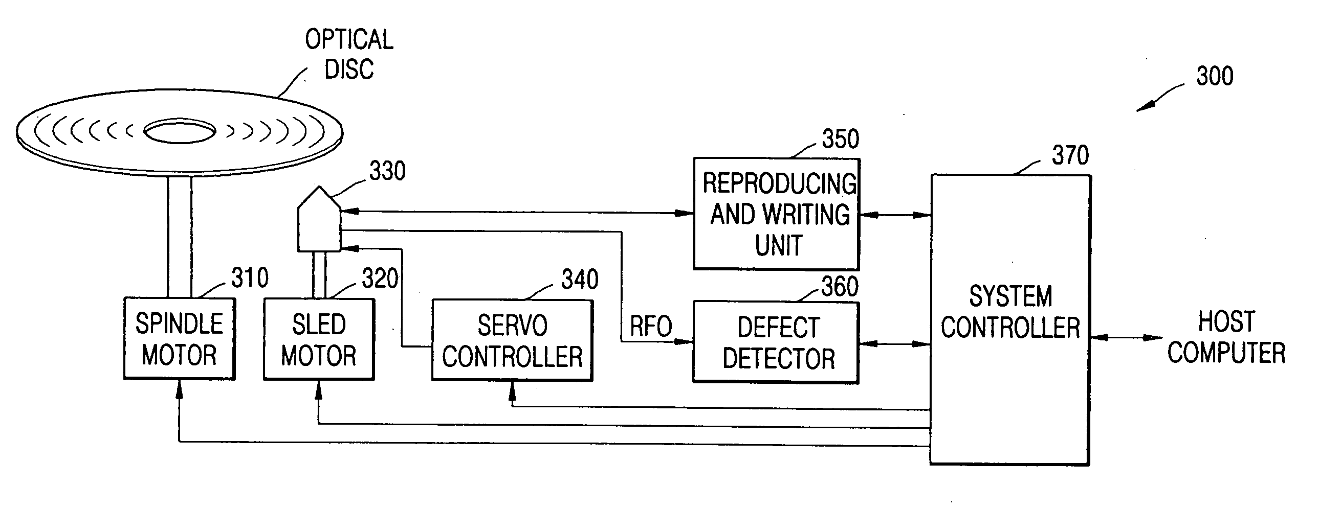
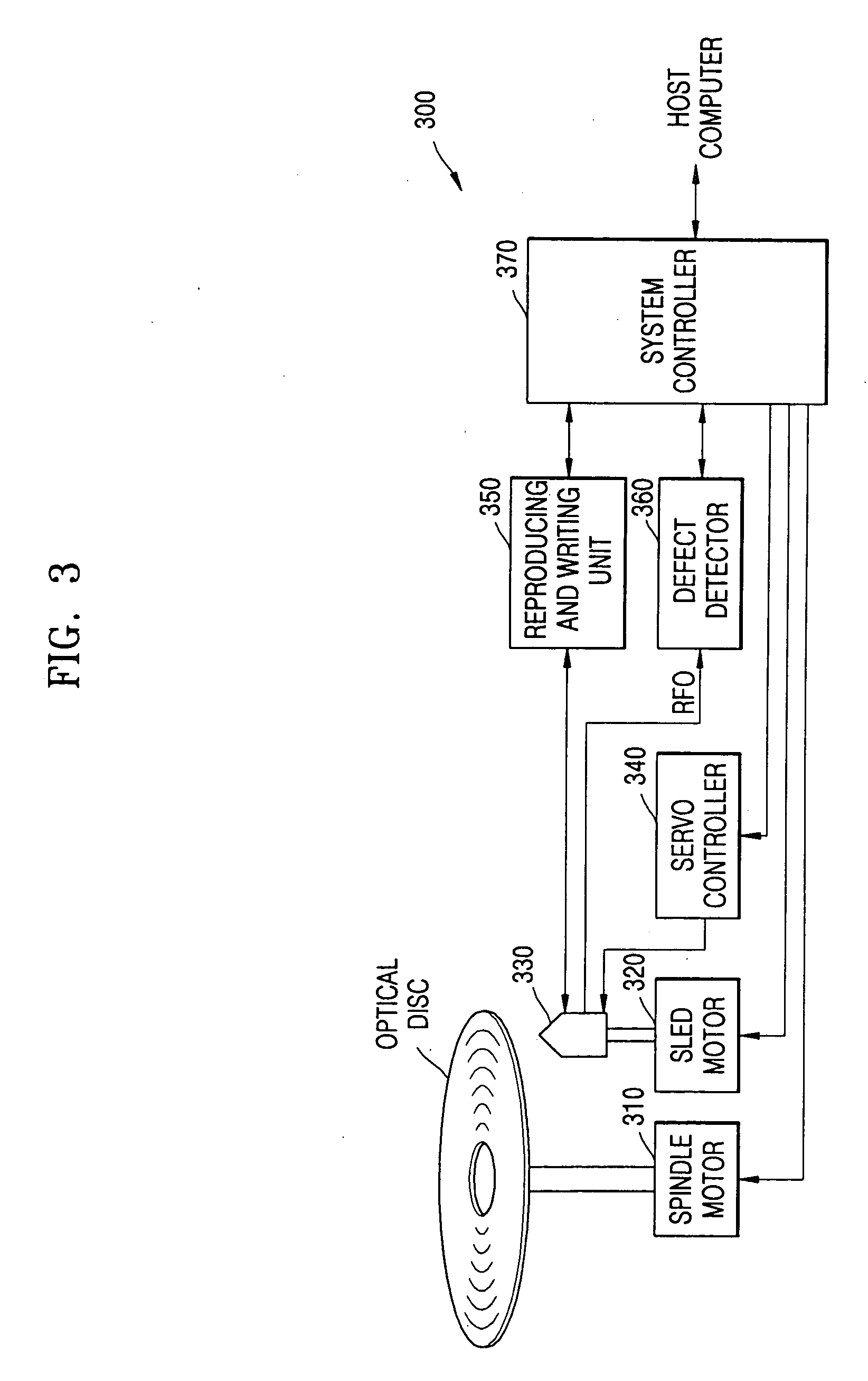
[0030]FIG. 3 shows a block diagram of an optical disc reproducing / rewriting system 300 having a defect detector 360 according to an embodiment of the present invention. The optical disc reproducing / rewriting system 300 is an example data disc system, and the present invention may be applied for other types of data disc systems. The system 300 also includes a spindle motor 310, a sled motor 320, a pick-up unit 330, a servo controller 340, a reproducing and writing unit 350, and a system controller 370.

[0031] An optical disc is loaded on a rotating axis of the spindle motor 310 and rotated. The pick-up unit 330 is moved horizontally across the optical disc by the sled motor 320. Here, the optical disc is a re-writable disc. The pick-up unit 330 reads information recorded on the optical disc or writes encoded data on the optical disc under control of the servo controller 340. The servo controller 340 drives a tracking actuator and a focusing actuator within the pick-up unit 330. The s...


PUM


Abstract

A defect detector in a data disc system includes a defect estimation unit and a defect length counter. The defect detector inputs a RF signal from a pick-up unit for generating a defect signal. The defect length counter interprets the defect signal using a wobble signal and a header position (ESFS) signal to generate defect length information. A system controller determines which sector of the data disc has unacceptable defect from the defect length information to reassign such a sector to another available sector on the data disc.

Description

BACKGROUND OF THE INVENTION [0001] This application claims priority to Korean Patent Application No. 2004-62772, filed on Aug. 10, 2004, in the Korean Intellectual Property Office, the disclosure of which is incorporated herein in its entirety by reference. [0002] 1. Field of the Invention [0003] The present invention relates generally to disc reproducing / rewriting systems, and more particularly to defect management therein for defects beyond ECC (error correction code) capability. [0004] 2. Description of the Related Art [0005] In general, a system which reproduces / writes information from / to an optical disc such as a re-writable CD-RW, CD-MRW, DVD±R / RW, DVD-RAM, DVD+MRW and so on uses a pick-up unit to access tracks of the optical disc. Manufacturing specifications of the re-writable optical disc guarantee a predetermined number of times for repeatedly rewriting information on the optical disc. [0006] However, with repeated use of the re-writable optical disc, defects may be genera...

Claims


Application Information

Patent Timeline
IPC IPC(8): G11B20/18G11B20/10
CPCG11B20/1883G11B7/004
Inventor OH, KI-HWAN
Owner SAMSUNG ELECTRONICS CO LTD
Why Eureka
Try Eureka