Method and apparatus for a hybrid battery configuration for use in an electric or hybrid electric motive power system

a technology of hybrid battery and power system, applied in the direction of motor/generator/converter stopper, dynamo-electric converter control, secondary cell servicing/maintenance, etc., can solve the problem of not being electrically rechargeable, and achieve the effect of optimizing the power system, high power density battery and high energy density battery

Inactive Publication Date: 2006-05-23
GENERAL ELECTRIC CO
View PDF24 Cites 162 Cited by
  • Summary
  • Abstract
  • Description
  • Claims
  • Application Information

AI Technical Summary

Benefits of technology

[0005]The present invention seeks to optimize the power system for an electrically propelled vehicle by the use of the combination of a high power density battery and a high energy density battery. For example, very high energy density battery technology exists in the form of, for example, zinc-air mechanically rechargeable batteries, which have been demonstrated to achieve energy densities of 200 W-hr/kg, compared to a lead-acid battery w...

Problems solved by technology

One problem with using high energy density batteries in EV applications is that such batteries are not elect...

Method used


Image

  • Method and apparatus for a hybrid battery configuration for use in an electric or hybrid electric motive power system
  • Method and apparatus for a hybrid battery configuration for use in an electric or hybrid electric motive power system
  • Method and apparatus for a hybrid battery configuration for use in an electric or hybrid electric motive power system

Examples


Embodiment Construction

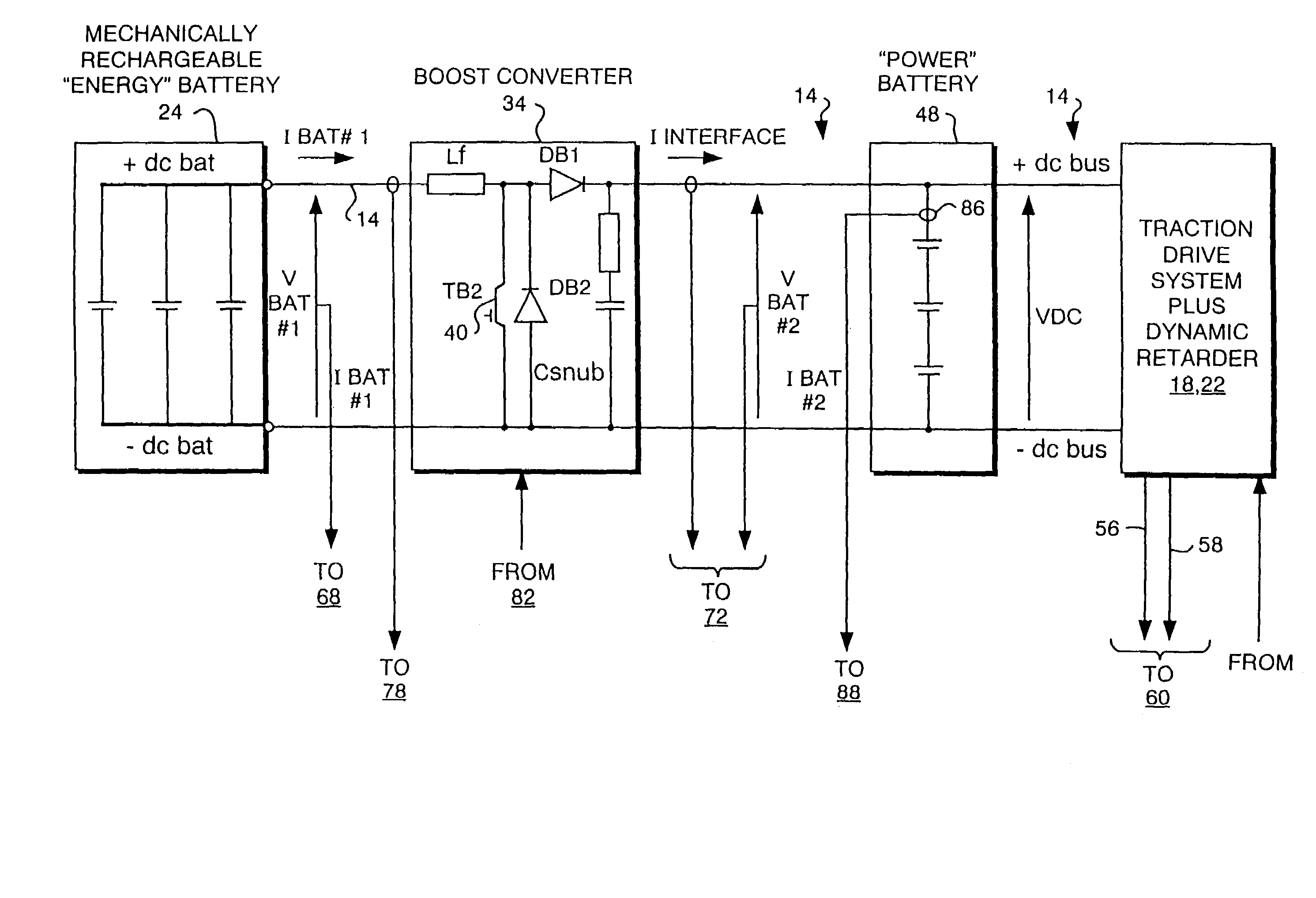
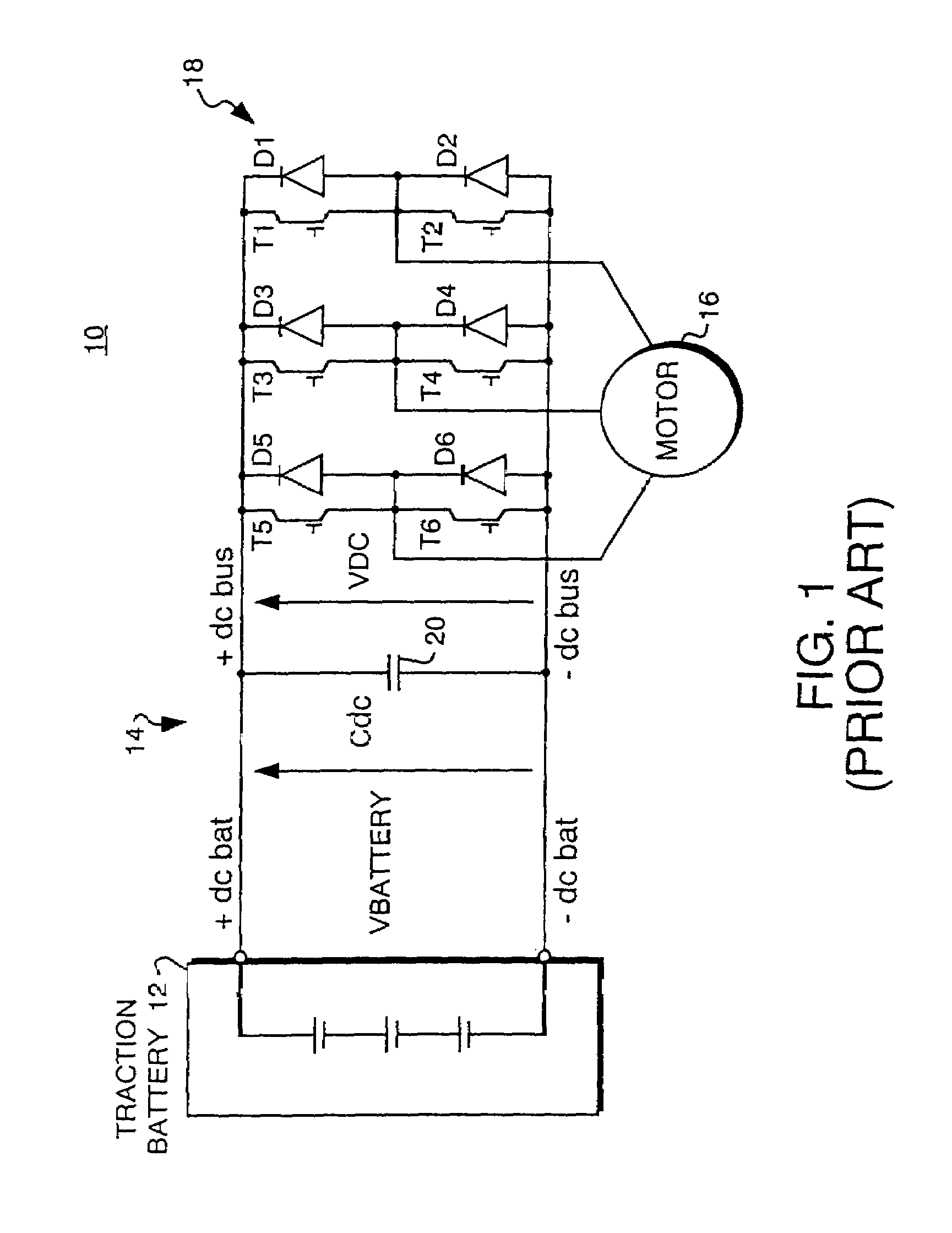
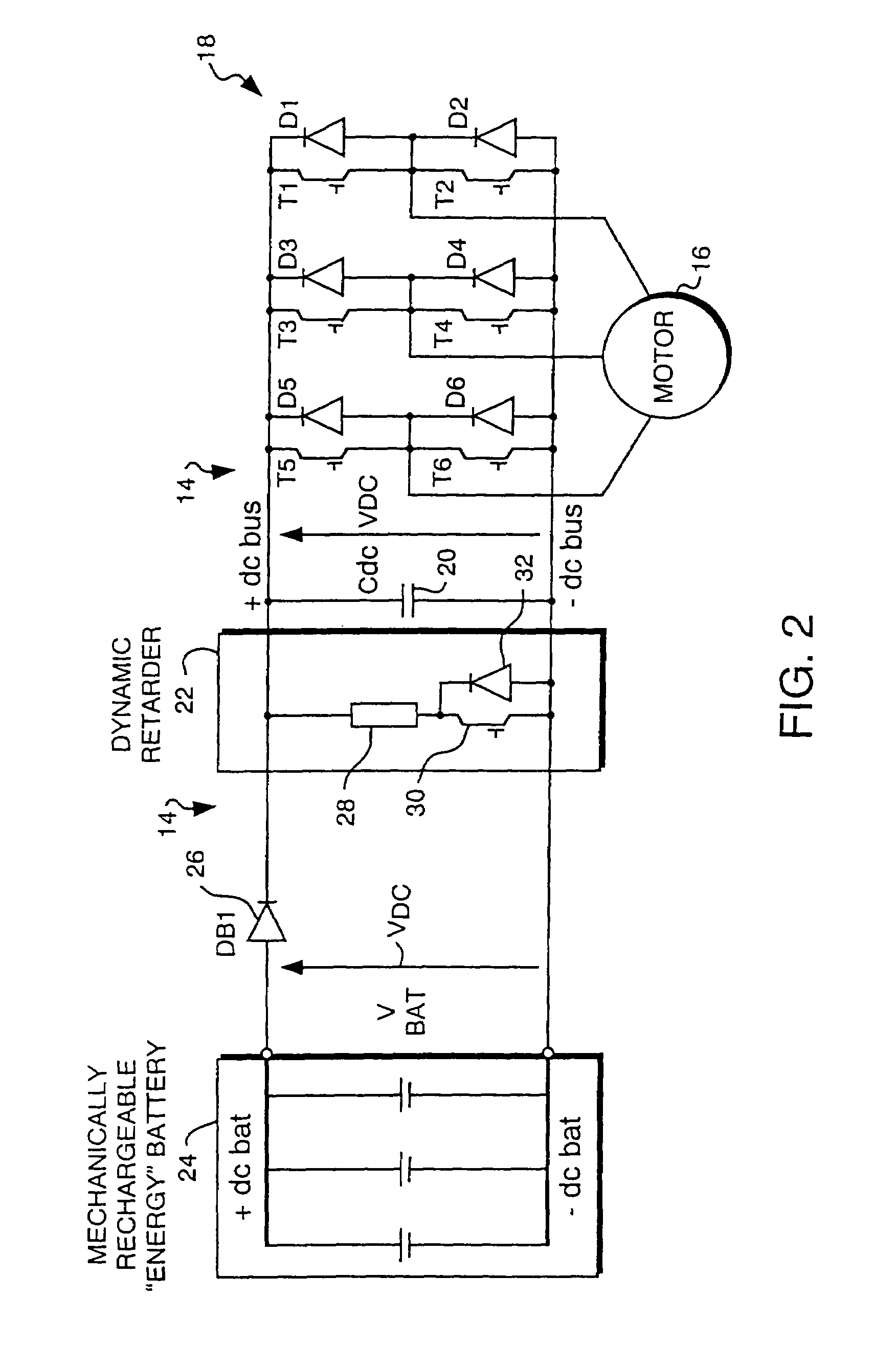
[0019]FIG. 1 schematically illustrates a conventional AC motor traction drive system 10 powered from an electrically rechargeable battery 12, such as a lead-acid or other high power density battery used in traction motor applications. The traction battery 12 is coupled to a DC link 14 which couples power to, or receives regenerative power from, an electric traction load or motor 16 coupled to the DC link 14 by a traction drive converter 18 shown as an inverter 18 for purposes of FIG. 1.

[0020]The motor 16 is shown as an alternating current (AC) motor requiring variable frequency excitation, which is derived from the DC link 14 by the inverter 18, but could be a direct current (DC) motor coupled to link 14 by a DC control circuit, such as a pulse width modulation (PWM) converter. The AC motor 16 may comprise any suitable type of AC machine including, for example, an induction machine, a permanent magnet synchronous machine, an electronically commutated motor or a switched reluctance m...


PUM


Abstract

A power system for an electric motor drive such as may be used in an electrically propelled vehicle incorporates the combination of a high power density battery and a high energy density battery to provide an optimal combination of high energy and high power, i.e., a hybrid battery system. The hybrid battery system in one form includes components which prevent electrical recharge energy from being applied to the high energy density battery while capturing regenerative energy in the high power density battery so as to increase an electric vehicle's range for a given amount of stored energy. A dynamic retarding function for absorbing electrical regenerative energy is used during significant vehicle deceleration and while holding speed on down-hill grades, to minimize mechanical brake wear and limit excessive voltage on the battery and power electronic control devices. The high energy density battery coupled in circuit with a boost converter, a high power density battery, a dynamic retarder, and an AC motor drive circuit. The hybrid battery system is controlled by a hybrid power source controller which receives signals from a vehicle system controller using current and voltage sensors to provide feedback parameters for the closed-loop hybrid battery control functions.

Description

[0001]This application is a division of application Ser. No. 10 / 191,790 filed May 29, 2001 now U.S. Pat No. 6,737,822, which is a division of 09 / 190,069 filed Nov. 12 1998, now U.S. Pat. No. 6,331,365 issued Dec. 18, 2001, which is hereby incorporated by reference in its entirety.BACKGROUND[0002]The present invention relates to a battery power control system, and more specifically, to a low-cost configuration and control method for a hybrid battery system which achieves both high energy density and high power density for use in an electric or hybrid electric motor drive system such as used in electrically propelled vehicles.[0003]Propulsion systems for electric motor propelled vehicles (“electric vehicle” or EV) generally use rechargeable traction batteries to provide electric power for driving electric motors coupled in driving relationship to wheels of the vehicle. For example, U.S. Pat. No. 5,373,195 illustrates a system in which the traction batteries are connected to a direct c...

Claims


Application Information

Patent Timeline
IPC IPC(8): H02J7/00B60L11/18B60L50/15H01M10/44
CPCB60L11/1803B60L2210/14B60L2210/20B60L2220/18Y02T10/7005B60L2240/549Y02T10/725B60L2240/545B60L2240/547Y02T10/7225B60L50/51Y02T10/72Y02T10/70
Inventor KING, ROBERT DEAN
Owner GENERAL ELECTRIC CO
Why Eureka
Try Eureka