Wireless sensor and control transmitter system

a transmitter system and sensor technology, applied in the field of water or fluid control systems, can solve the problems of requiring a greater number of control units, knowing that the valve is not operating properly, and requiring additional controller units, so as to improve the control of the system and save resources

Inactive Publication Date: 2006-05-23
TECHSTREAMS CONTROL SYST AN ARIZONA
View PDF17 Cites 160 Cited by
  • Summary
  • Abstract
  • Description
  • Claims
  • Application Information

AI Technical Summary

Benefits of technology

[0018]The WSCXS comprises two main modules, a Master Module Unit (MMU) and a Field Module Unit (FMU). The system employs radio frequency (RF) transceivers, on / off state function commands and sensor signal inputs that are communicated over an RF link rather than through wires. The WSCXS enables the transmission of signals and commands via a wireless communications bridge that can circumvent physical obstacles, structures or distances that would otherwise prohibit or make impractical a hardwired implementation. The WSCXS system is therefore a cost effective alternative to more expensive hardwire connection applications as detailed above.
[0023]This embodiment of the present WSCXS invention eliminates the need for running wire between any controller system unit and any field electromechanical control devices and / or to field sensors. Existing prior art has the sensors, irrigation valves, solenoids, motors, electric actuators or the like attached directly to an existing controller unit and not to a fully duplexed wireless subsystem such as this invention that otherwise eliminates the need for direct wire connection.
[0025]The use of previously incompatible electromechanical devices and sensors can modernize and add great economy and convenience to a fluid transfer, water or irrigation system, providing valuable feedback and improved control of the system. These devices may be incorporated into an existing system that would otherwise be incapable of implementing them or performing advanced functions.
[0026]This WSCXS can therefore be used to provide digital functionality when retrofitting an existing system, or installing a new system, without the need to excavate and run wires under roads, structures and other obstacles. The present WSCXS invention eliminates the need for wires between a controller unit and all types of field electromechanical control devices and field sensors. The WSCXS can also provide the ability to add an open-ended variety of supplemental functionality to an existing hydraulic or irrigation system.

Problems solved by technology

If the existing controller does not sense a current load after energizing a valve, then the controller will know that the valve is not operating properly.
The additional controller units may be required because of limitations caused by electrical line impedance, the distance wire can be run and the maximum amount of electrical impedance, or because of the remote proximity to water supply lines or meters.
Though expensive, it is usually substantially cheaper to place more controllers near a water supply line than it is to move the supply line closer to a controller.
These types of irrigation systems therefore often require a greater number of control units, and at a greater expense, to adequately control the supply of water to far reaching areas.
Larger property sites such as those used in cities, with highways, planned communities, golf courses, institutional or commercial facilities and the like, are difficult to maintain and manage because of the shear number of control points and the remote proximity between control units.
Central control technology was developed to improve the efficiency of managing the distribution of water to large areas and to provide fault detection and reaction capability, but all carry a substantial economic cost to the purchaser of such systems.
Roughly, the same dollar investment must be made to control an irrigation system on a smaller land area, but with reduced possibility of return on investment, because the smaller property will not have as great a water waste or savings potential as a larger one.
However, though waste or savings potential may or may not be diminished, liability potential may be as great or greater depending upon the areas location.
For example, a broken line in a bad location can cause substantial property or other collateral damage.
Furthermore, most cities or large facilities are comprised of numerous smaller areas so when combined, can amount to significant total area or acreage.
Managing acreage, again, becomes an important issue relative to use efficiency and waste minimization.
Where there are numerous smaller areas within a larger site, such as a city, they are usually not included when converting several stand-alone control systems to a “smart” or central control system because of the high cost of retrofitting each control unit.
Further, retrofitting an existing stand-alone or central system to incorporate an MCV and field sensing inputs, processing and control capabilities is often neglected completely and not installed due to the high cost and difficulty that can be associated with laying wire to connect the devices.
In retrofit applications, it is also not uncommon to encounter adverse site conditions which require trenching great distances or through established areas to complete wire runs.
It is the incompatibility between devices and controllers that communicate through different signal waveforms or interface protocols, analog versus digital, along with the difference between the proprietary controllers and devices unique to different manufactures, Toro versus Rainbird versus Hunter or Orbit, that makes retrofitting older systems very expensive and complicated.

Method used


Image

  • Wireless sensor and control transmitter system
  • Wireless sensor and control transmitter system
  • Wireless sensor and control transmitter system

Examples


Embodiment Construction

[0034]The following description, and the figures to which it refers, are provided for the purpose of describing examples and specific embodiments of the invention only and are not intended to exhaustively describe all possible examples and embodiments of the invention. Many specific implementations of the following described WSCXS will be apparent to those of skill in the art.

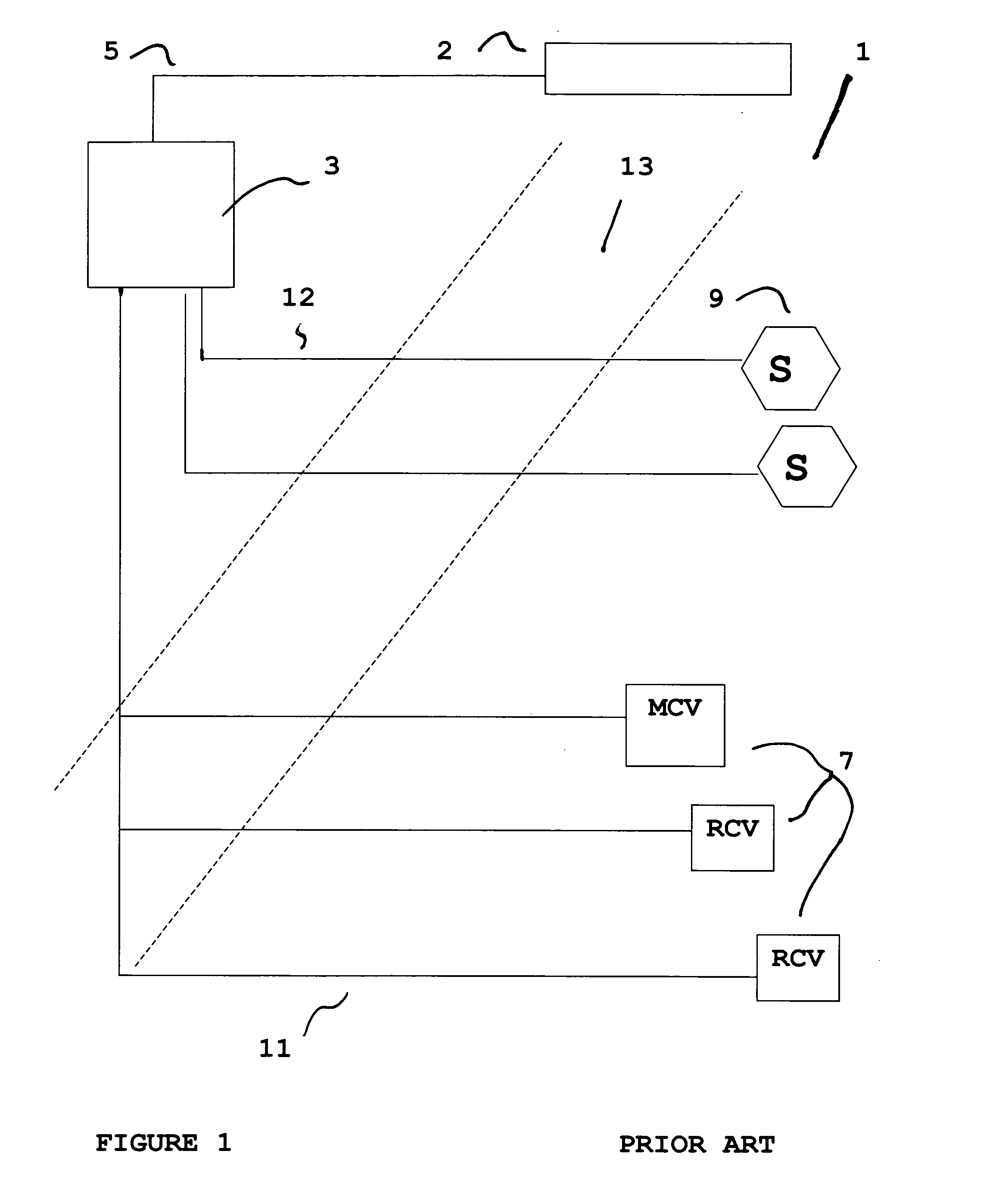
[0035]FIG. 1 shows a typical solid-state centralized irrigation system 1 of the prior art. A central base personal computer 2 is connected via a communications link 5, to a solid-state controller unit 3. The controller unit 3 is connected to one or more field MCV, RCV or other relay type devices 7, and / or to field sensors 9, such as flow, soil moisture, and atmospheric or other devices by hardwires 11 and 12. The hardwired connections between the controller unit 3 and the other components 5, 7 and 9 frequently run under roads 13 (shown in dashed lines) or other structure.

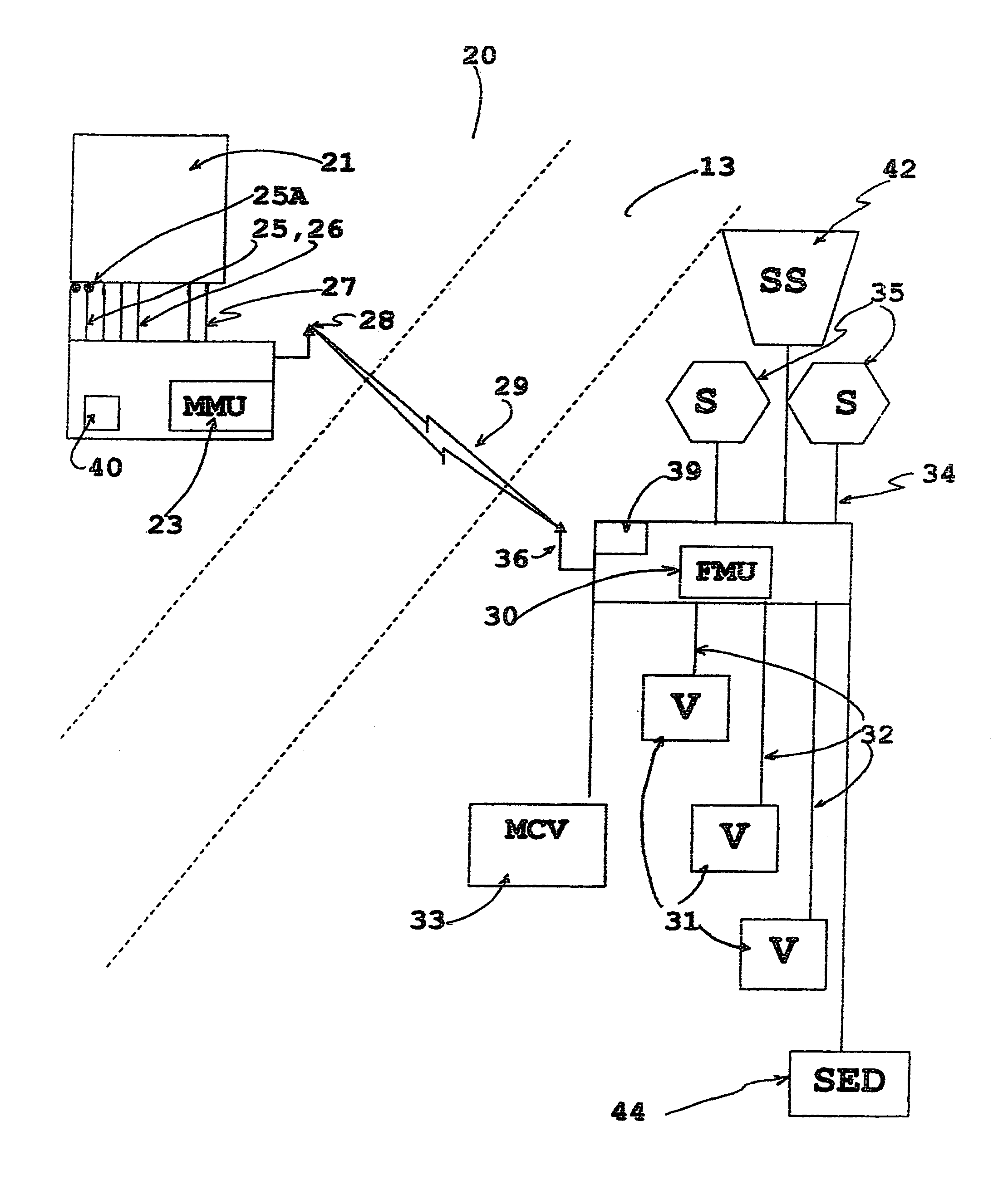
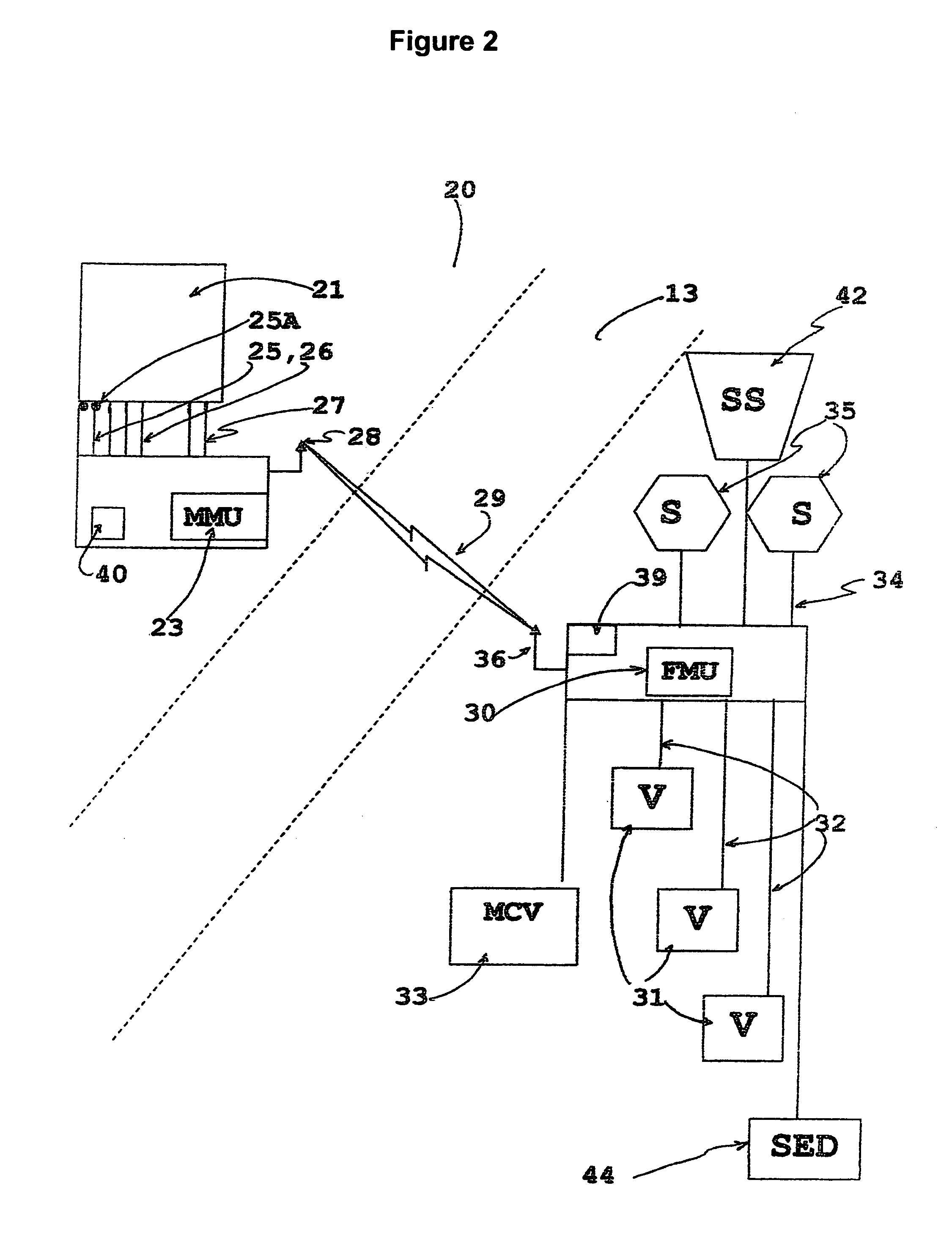
[0036]Referring now to FIG. 2, a diagram...


PUM


Abstract

A passive wireless sensor and control transmitter subsystem is provided for operating irrigation or other hydraulic system. The system includes a master module unit hardwired to and in communication with an existing hydraulic system controller, and a field module unit that is hardwired to and in communication with field electromechanical control devices such as valves, solenoids and servo motors, and field sensors indicating, for example, atmospheric conditions. The master module unit and field module unit communicate with digital wireless communication and can act as a simple wireless bridge providing pass through data connectivity. The master module and field module units are capable of digitizing input signals from the devices to which they are hardwired and transmitting them to the opposite module; they are further capable of recreating the digitized signals received back into the analog form to reproduce the original input signal and communicating it to the device to which it is hardwired. Full duplex communication enables remote sensors to be hardwired to the field modules unit rather than directly to existing control apparatus, as well as being able to transfer valve, pump and relay status back to existing control apparatus. One embodiment enables the subsystem to receive sensor inputs and process them accordingly even though the hydraulic control system may not be capable of utilizing them. Supplemental functionality may be added to an existing hydraulic control system by including the WSCX and its system features of sensor functionality and control.

Description

FIELD OF THE INVENTION[0001]The present invention relates to water or fluid control systems such as an irrigation controller system. More particularly, the present invention relates to a retrofit for an existing controller system with a subsystem apparatus that provides a wireless communications link between almost any controller and the control valves or sensors of the system, replacing the wire paths that are typically required to connect them, that can also provide additional functionality to an existing control system.BACKGROUND OF THE INVENTION[0002]There are numerous types of automatic controllers that typically incorporate conventional motor-driven electric clocks or solid-state electronics or both technologies combined. These systems provide for individual start times for particular irrigation cycles and watering schedules and may include calendar programs that provide the ability to select particular days and distribution periods with these control units.[0003]Solid-state i...

Claims


Application Information

Patent Timeline
Patent Type & Authority Patents(United States)
IPC IPC(8): G05D7/00G01D5/48G01F15/06G01F23/00
CPCG01D21/00G01F23/0069G01F15/063Y10T137/86389G01F23/802
Inventor ALVAREZ, RAYMOND MICHAEL
Owner TECHSTREAMS CONTROL SYST AN ARIZONA
Why Eureka
Try Eureka