Semi-active full cell apparatus

a full cell, semi-active technology, applied in the direction of cell components, cell component details, electrochemical generators, etc., can solve the problems of increasing the additional device cost, consuming the electricity of the fuel cell itself, and reducing the real output electricity

Inactive Publication Date: 2006-03-02
ANTIG TECH CO LTD
View PDF6 Cites 6 Cited by
  • Summary
  • Abstract
  • Description
  • Claims
  • Application Information

AI Technical Summary

Problems solved by technology

The disadvantage of the active fuel cell is that the active device has to consume the power of the fuel cell itself and therefore reduces the real output electricity.
Otherwise, the active device is only in charge of transporting the fuel, the reaction of the fuel cell itself and the active device will produce the heat which needs another device to dissipate and therefore increases additional device cost and consumes the electricity of the fuel cell itself so as to be the major disadvantage.
The disadvantage of the passive fuel cell is that the fuel supply of the fuel cell fails to be directly controlled so as to make the fuel cell inefficient and the reaction efficiency easily influenced by the environment.

Method used


Image

  • Semi-active full cell apparatus
  • Semi-active full cell apparatus
  • Semi-active full cell apparatus

Examples


Embodiment Construction

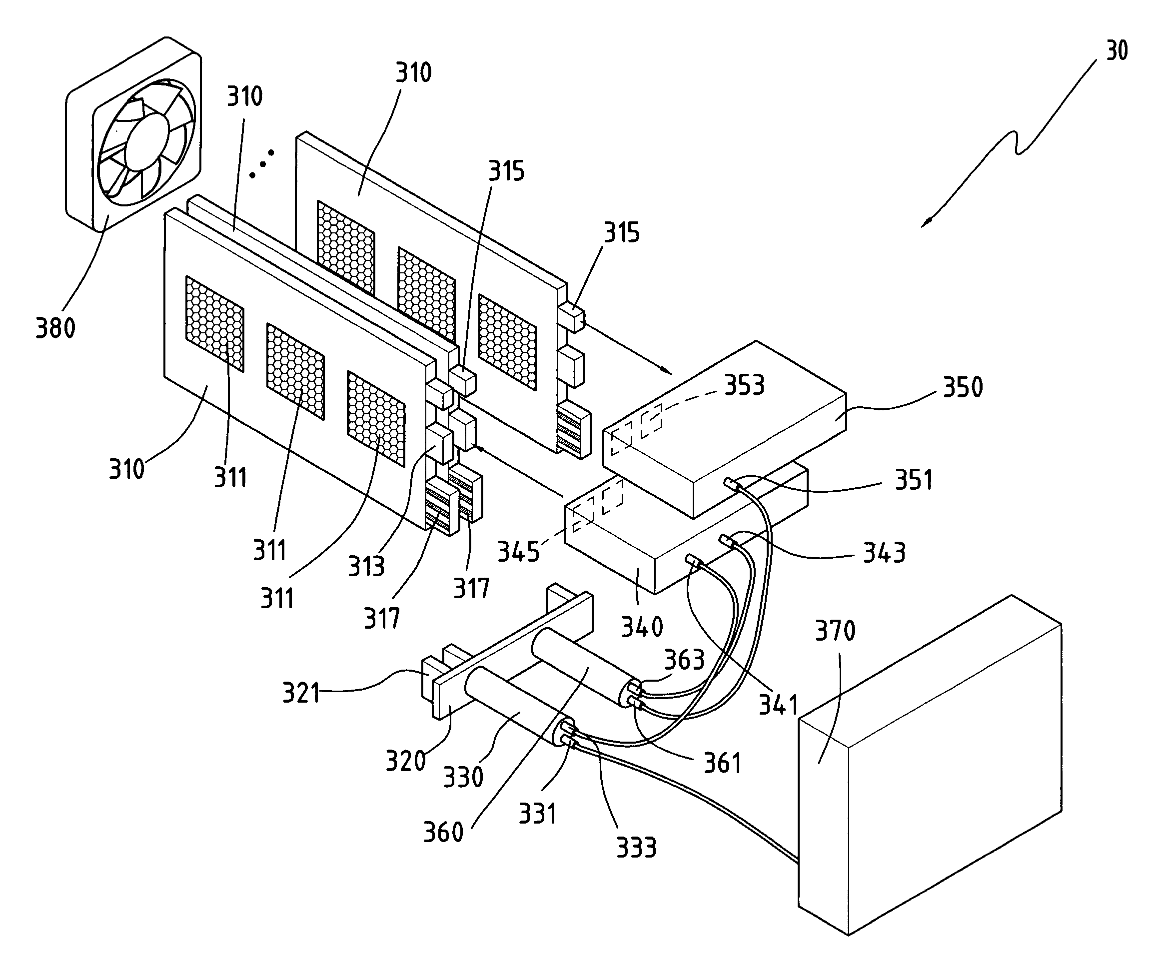
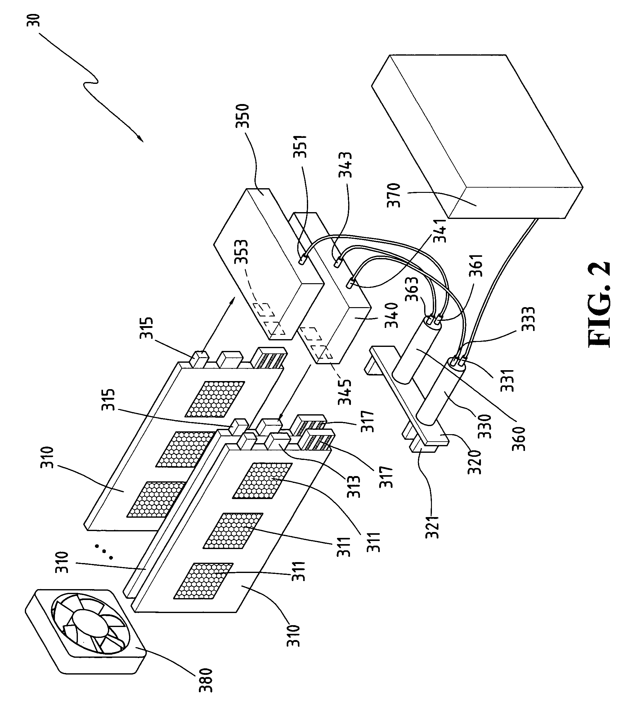
[0016]FIG. 2 shows the decomposed figure of the present invention semi-active fuel cell. The present invention semi-active fuel cell apparatus 30 mainly comprises plural fuel cell boards 310, electrically plugging board 320, fuel replenishing unit 330, first fuel control unit 340, second fuel control unit 350, fuel cycling unit 360, fuel storage unit 370 and gas cycling supply unit 380.

[0017] Each piece of the present invention fuel cell board 310 has plural membrane electrode assemblies (MEAs) 311, every fuel cell board 310 is placed cycling inlet 313, cycling outlet 315 and golden finger 317 wherein the anode fuel is possible to flow from cycling inlet 313 into the MEAs 311, and flow outward from cycling outlet 315.

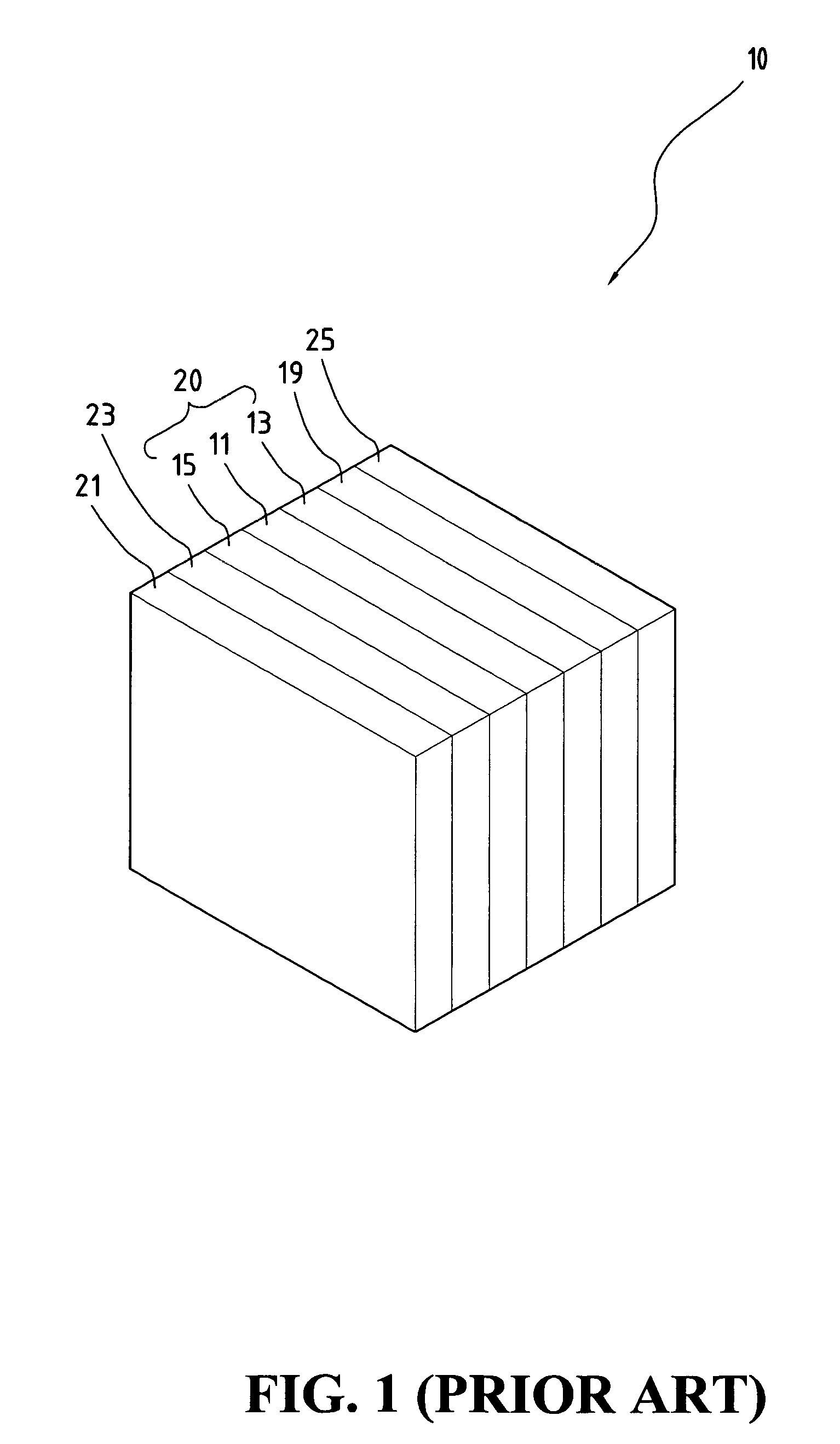
[0018] The present invention fuel cell board 310 is possible to be produced by modifying layer lamination integrated fuel cell apparatus 10, referring to FIG. 1. The present invention cycling inlet 313 and cycling outlet 315 are possibly placed on one side of fuel flo...


PUM

PropertyMeasurementUnit
gravityaaaaaaaaaa
heat dissipationaaaaaaaaaa
voltageaaaaaaaaaa

Abstract

The present invention is related to a semi-active fuel cell apparatus, mainly comprising plural fuel cell boards, gas cycling supply unit, fuel replenishing unit, fuel cycling unit, first fuel control unit and second fuel control unit. By way of connecting these constituent elements, the anode fuel is capable of being supplied to the fuel cell boards by cycling means; the gas cathode fuel is capable of being supplied to the fuel cell boards. Meanwhile, the gas cycling supply unit is also used for heat dissipation.

Description

FIELD OF THE INVENTION [0001] The present invention is related to a fuel cell, especially to a fuel cell having fuel cycling mechanism. BACKGROUND OF THE INVENTION [0002]FIG. 1 shows a structural figure of layer lamination integrated fuel cell apparatus. In FIG. 1, layer lamination integrated fuel cell apparatus 10 includes fuel flow layer 25, first electricity / signal transport layer 19, anode current collection layer 13, conduction electrolyte layer 11, cathode current collection layer 15, second electricity / signal transport layer 23 and electromechanical control layer 21, wherein anode current collection layer 13, conduction electrolyte layer 11 and cathode current collection layer 15 constitute the core components 20 of fuel cell. [0003] The used fuel cell is roughly divided into two types of the active fuel cell and passive fuel cell. The means of fuel supply for the active fuel cell is to use the active device like the pump to transport the external anode fuel to the internal f...

Claims


Application Information

Patent Timeline
Patent Type & Authority Applications(United States)
IPC IPC(8): H01M8/24H01M2/02H01M2/36H01M8/00H01M8/04H01M8/10
CPCH01M8/04014H01M8/04089H01M8/04097H01M8/04186Y02E60/523H01M8/04753H01M8/1011H01M8/1097H01M8/2465H01M8/04201Y02E60/50H01M8/10H01M8/241
Inventor SHU, HSI-MINGCHANG, TSANG-MINGDENG, FENG-YI
Owner ANTIG TECH CO LTD
Why Eureka
Try Eureka