Fuel cell stack
a fuel cell and stacking technology, applied in the field of fuel cell stacks, can solve the problems of increasing the weight the size of the fuel cell stack in the stacking direction of the unit cell b>1/b> disadvantageously, and the stack body may be vibrated undesired, so as to achieve the effect of simple and economical structur
- Summary
- Abstract
- Description
- Claims
- Application Information
AI Technical Summary
Benefits of technology
Problems solved by technology
Method used
Image

Examples
first embodiment
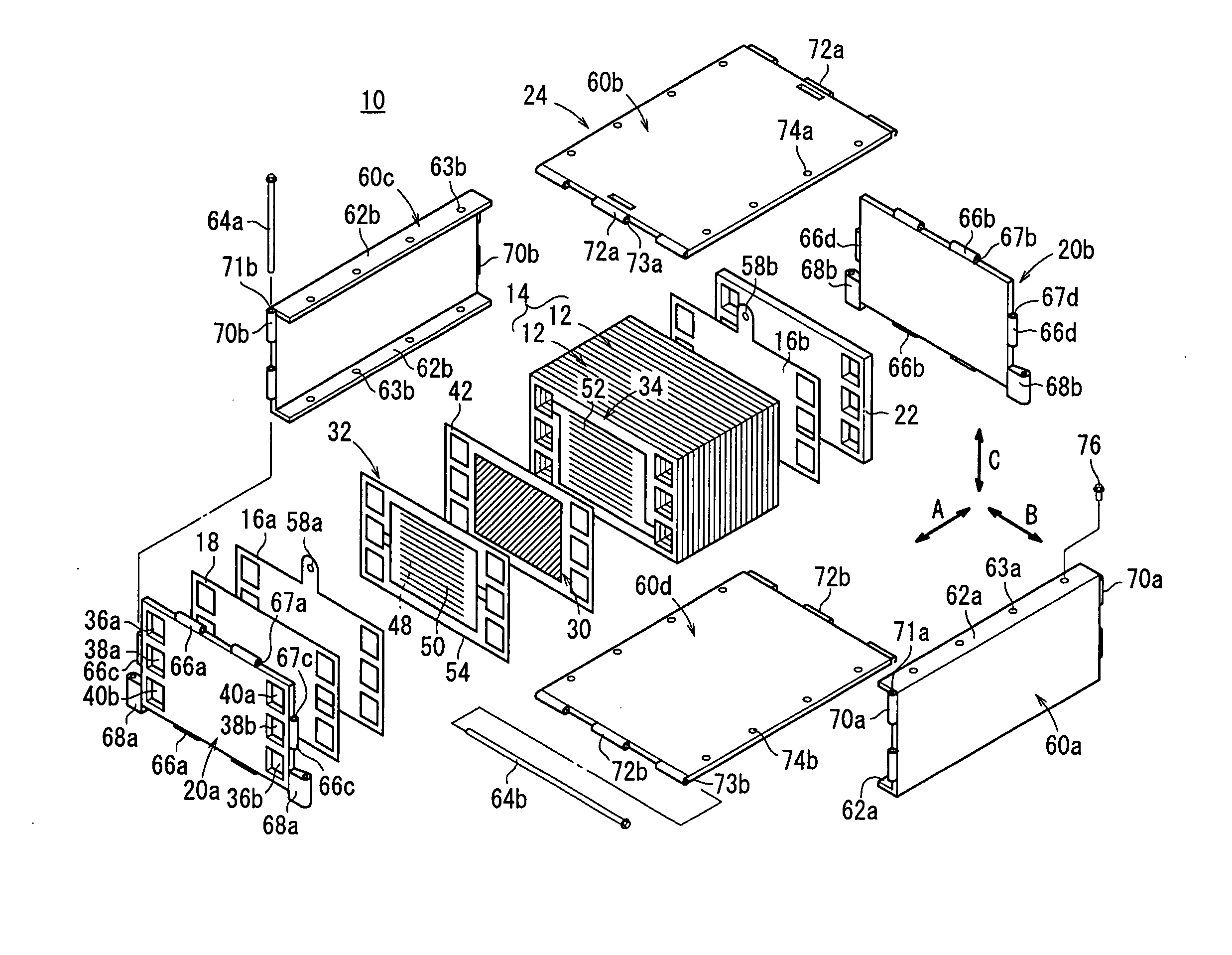
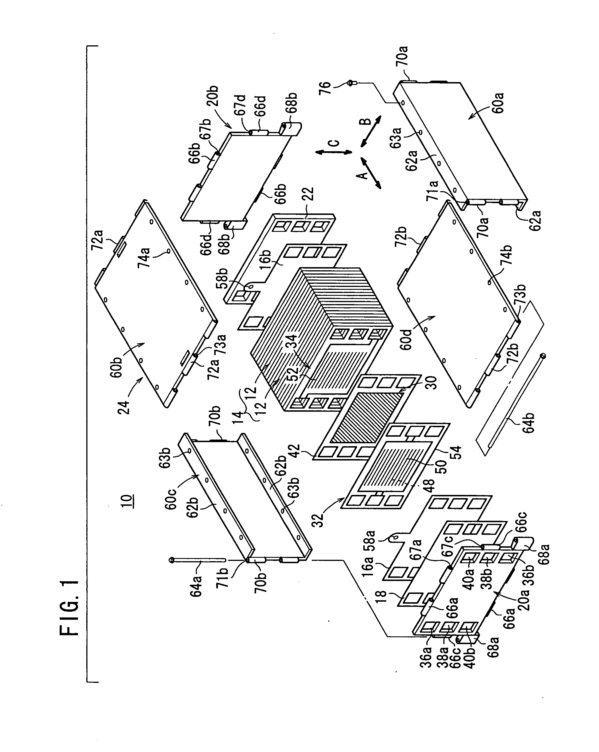
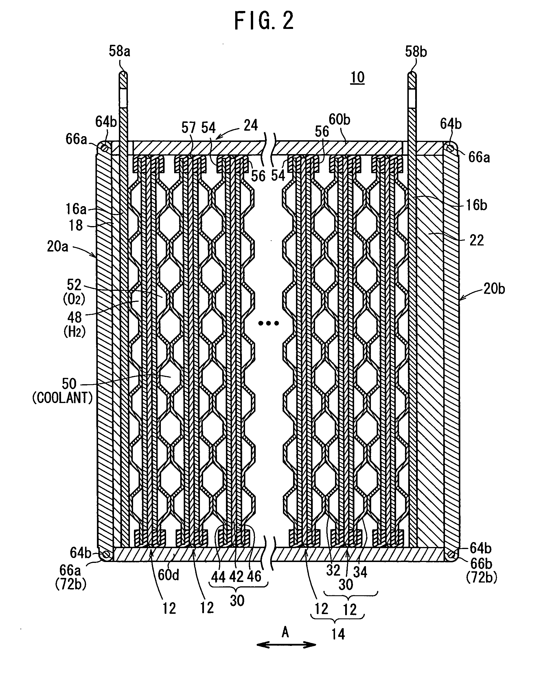
[0069]FIG. 1 is a partial exploded perspective view schematically showing a fuel cell stack 10 according to the present invention. FIG. 2 is a cross sectional side view showing part of the fuel cell stack 10.
[0070] As shown in FIG. 1, the fuel cell stack 10 includes a stack body 14 formed by stacking a plurality of unit cells 12 horizontally in a stacking direction indicated by an arrow A. At one end of the stack body 14 in the stacking direction indicated by the arrow A, a terminal plates 16a is provided. An insulating plate 18 is provided outside the terminal plate 16a. Further, an end plate 20a is provided outside the insulating plate 18. At the other end of the stack body 14 in the stacking direction, a terminal plate 16b is provided. An insulating spacer member 22 is provided outside the terminal plate 16b. Further, an end plate 20b is provided outside the insulating spacer member 22. Each of the end plates 20a, 20b has a rectangular shape. The fuel cell stack 10 is assembled t...
second embodiment
[0099]FIG. 7 is a partial exploded perspective view schematically showing a fuel cell stack 80 according to the present invention. FIG. 8 is a cross sectional side view showing part of the fuel cell stack 80.
[0100] A casing 82 of the fuel cell stack 80 includes end plates 20a, 20b, and side plates 84a to 84d connected by coupling pins 64a, 64b. The side plates 84b, 84d are provided on upper and lower sides of the stack body 14. The side plates 84a, 84c are provided at opposite sides of the stack body 14 in the direction indicated by the arrow B. The width of the side plates 84b, 84d is larger than the width of the side plates 84a, 84c. At opposite marginal ends of the side plates 84b, 84d in the lateral direction indicated by the arrow B, attachment flanges 86a, 86b are provided.
[0101] Each of the flanges 86a, 86b has a plurality of screw holes 88a, 88b. At marginal ends of the side plates 84a, 84c in the lateral direction indicated by the arrow C, a plurality of holes 90 are forme...
third embodiment
[0106]FIG. 10 is a view showing a casing 102 of a fuel cell stack 100 according to the present invention.
[0107] The casing 102 includes side plates 104a to 104d. The side plates 104a to 104d have substantially L-shaped cross section. Attachment flanges 106a, 106b are provided at diagonal positions, i.e., at one end of the side plate 104a in the lateral direction indicated by the arrow C, and at one end of the side plate 104c in the lateral direction indicated by the arrow C. Likewise, attachment flanges 108a, 108b are provided at diagonal positions, i.e., at one end of the side plate 104b in the lateral direction indicated by the arrow B, and at one end of the side plate 104d in the lateral direction indicated by the arrow B.
[0108] The other end of the side plate 104a and the flange 108a, the other end of the side plate 104b and the flange 106b, the other end of the side plate 104c and the flange 108b, and the other end of the side plate 104d and the flange 106a are fixed by a plur...
PUM
| Property | Measurement | Unit |
|---|---|---|
| angle | aaaaa | aaaaa |
| width | aaaaa | aaaaa |
| thickness | aaaaa | aaaaa |
Abstract
Description
Claims
Application Information
 - R&D
- Intellectual Property
- Life Sciences
- Materials
- Tech Scout
- Unparalleled Data Quality
- Higher Quality Content
- 60% Fewer Hallucinations
Browse by: Latest US Patents, China's latest patents, Technical Efficacy Thesaurus, Application Domain, Technology Topic, Popular Technical Reports.
© 2025 PatSnap. All rights reserved.Legal|Privacy policy|Modern Slavery Act Transparency Statement|Sitemap|About US| Contact US: help@patsnap.com