Electrical connector power wafers

a technology of electrical connectors and power wafers, applied in the direction of coupling device details, coupling device connections, coupling protective earth/shielding arrangements, etc., can solve the problems of short supply of connector space on circuit boards, limit the amount of connector space available for each application, etc., to achieve the effect of suppressing arcing

Active Publication Date: 2006-03-02
TYCO ELECTRONICS LOGISTICS AG (CH)
View PDF11 Cites 9 Cited by
  • Summary
  • Abstract
  • Description
  • Claims
  • Application Information

AI Technical Summary

Problems solved by technology

In today's systems, there is a continuously increasing demand for resources, such as signal and power, and as a result, connector space on the circuit boards is in short supply.
In many instances, due to space limitations, system operators limit the amount of connector space available for each application.

Method used


Image

  • Electrical connector power wafers
  • Electrical connector power wafers
  • Electrical connector power wafers

Examples


Embodiment Construction

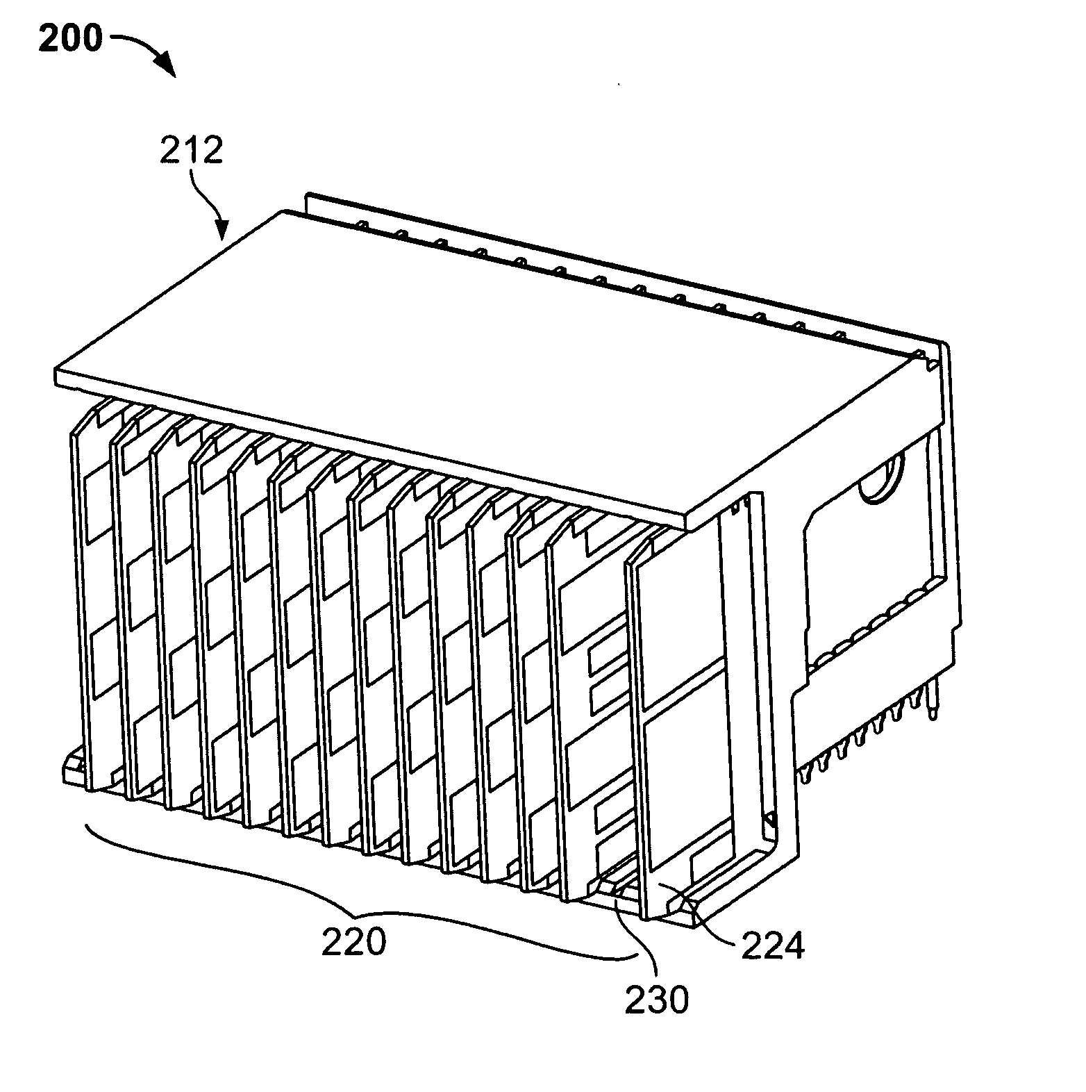
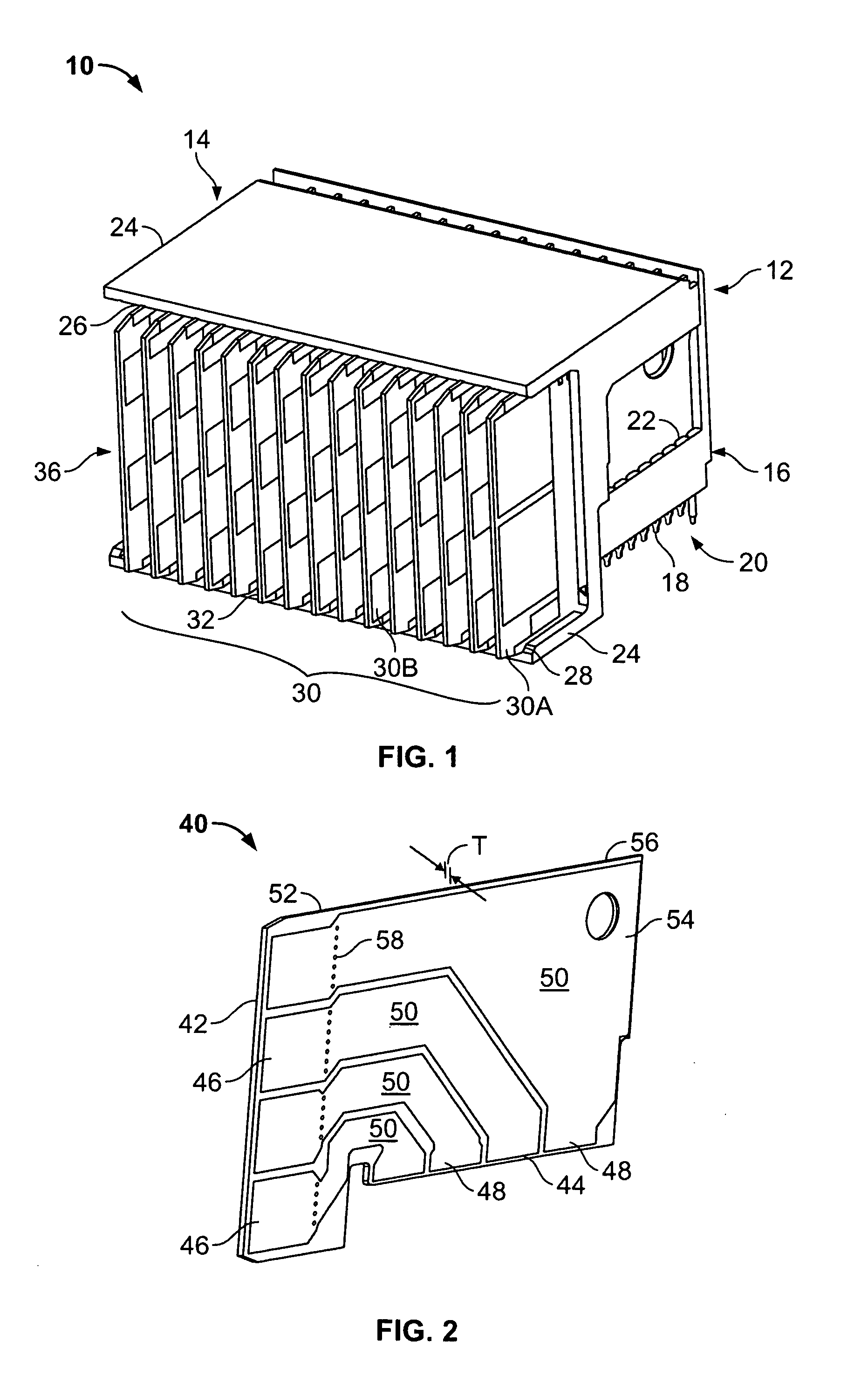
[0023]FIG. 1 illustrates a perspective view of an electrical connector 10 formed in accordance with an exemplary embodiment of the present invention. While the invention will be described in terms of a right angle connector, it is to be understood that the benefits described herein are also applicable to connectors formed at other than a right angle. The following description is for illustrative purposes only and is but one potential application of the inventive concepts herein. In addition, the connector 10 will be described as including one or more electrical wafers. As used herein, the term wafer shall include an all metal conductive sheet in addition to the meanings commonly given the term in the art.

[0024] The connector 10 includes a housing 12 that has an upper portion 14 and a base portion 16. The base 16 includes a plurality of contacts 18 that form a daughter card interface 20 that is also a mounting face at the base 16 of the connector 10. The base 16 includes a plurality...


PUM


Abstract

An electrical connector is provided that includes a dielectric housing having a plurality of slots therein, and a plurality of electrical contacts disposed within at least one of the slots. A plurality of electrical wafers, are each received in one of the plurality of slots. Each wafer has a first edge and a second edge. Some of the plurality of electrical wafers are signal wafers and some of the plurality of wafers are power wafers. Each of the power wafers includes at least one trace and at least one contact pad. The contact pad is sized to mate with a predetermined number of the plurality of contacts to transfer a predetermined amount of current through the trace.

Description

BACKGROUND OF THE INVENTION [0001] The invention relates generally to electrical connectors and, more particularly, to a signal level connector with power handling. [0002] Modern electronic systems such as telecommunications systems and computer systems often include large circuit boards called backplane boards which are rack mounted or retained in cabinets and are electrically connected to a number of smaller circuit boards called daughter cards. Electrical connectors establish communications between the backplane and the daughter cards. The daughter cards are typically separate from each other and meet different requirements for different purposes such as transmission of high speed signals, low speed signals, power, etc. that are transferred to the daughter cards from the backplane board. [0003] In today's systems, there is a continuously increasing demand for resources, such as signal and power, and as a result, connector space on the circuit boards is in short supply. In many in...

Claims


Application Information

Patent Timeline
Patent Type & Authority Applications(United States)
IPC IPC(8): H01R13/648
CPCH01R13/514H01R12/7088H01R23/7073H01R12/724
Inventor CONSOLI, JOHN JOSEPHROTHERMEL, BRENT RYANFEDDER, JAMES LEEDEFIBAUGH, GEORGE RICHARDHERMAN, HENRY OTTO JR.SIPE, LYNN ROBERT
Owner TYCO ELECTRONICS LOGISTICS AG (CH)
Why Eureka
Try Eureka