Endoscope having auto-insufflation and exsufflation

an endoscope and auto-insufflation technology, which is applied in the field of automatic medical insufflation devices for diagnostic and surgical endoscopy, can solve the problems of not providing quantitatively accurate methods of regulating, affecting the patient's pain, and causing late perforations, so as to reduce patient discomfor

Inactive Publication Date: 2006-03-02
BOSTON SCI SCIMED INC
View PDF21 Cites 184 Cited by
  • Summary
  • Abstract
  • Description
  • Claims
  • Application Information

AI Technical Summary

Benefits of technology

[0006] To address the problems associated with conventional endoscopic insufflation systems, the present invention decreases patient discomfort due to insufflation of a body lumen and allows a physician a clear field of view of an interior body cavity. The present invention automatically controls insufflation and exsufflation parameters based on different operating modes of the system and / or based on body cavity characteristics viewed by the endoscope. In one embodiment, the present invention is an endoscopic imaging system of the type that includes an elongated shaft having a proximal end and a distal end. The shaft includes one or more distal gas ports at or adjacent the distal end of the shaft and one or more proximal gas ports. The endoscope is removably connected to a control unit having an insufflation gas supply and a gas venting system. Insufflation gas is selectively delivered to the distal gas ports and withdrawn from the proximal gas ports or vice versa during an endoscopic examination so that a gas bubble is formed around the distal end of the endoscope. The gas bubble travels with the distal tip as the endoscope is inserted into or withdrawn from the lumen.

Problems solved by technology

Because many systems do not provide quantitatively accurate methods of regulating the delivery of the gas, those systems can allow variations in the pressure, volume, and flow rate of gas administered during an endoscopic procedure.
In addition, air pressure in the colon is a cause of pain for the patient, both during the procedure and afterwards, due to distension of the bowel if the pressure is not abated.
Furthermore, excess insufflation pressure can potentially stress, or even rupture, the colon during the colonoscopy or may cause the development of late perforations if the pressure and volume of the insufflating gas is not accurately controlled and promptly released.

Method used


Image

  • Endoscope having auto-insufflation and exsufflation
  • Endoscope having auto-insufflation and exsufflation
  • Endoscope having auto-insufflation and exsufflation

Examples


Embodiment Construction

[0014] As indicated above, the present invention is an endoscopic imaging system that performs automated insufflation for use with diagnostic and surgical endoscopy. Although the present invention is described with respect to its use within the colon, it will be appreciated that the invention can be used in any body cavity that can be expanded for examination and / or surgery.

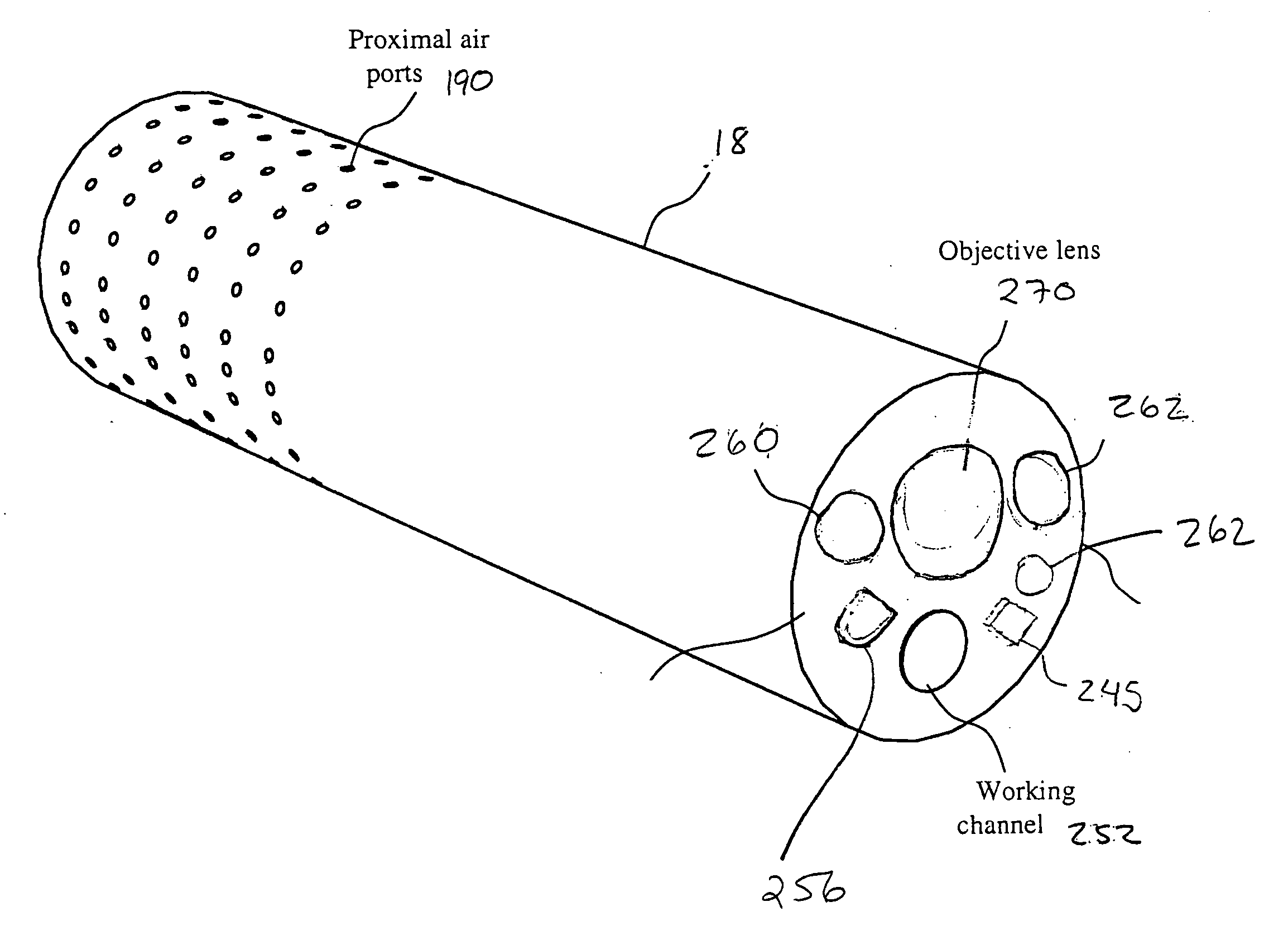
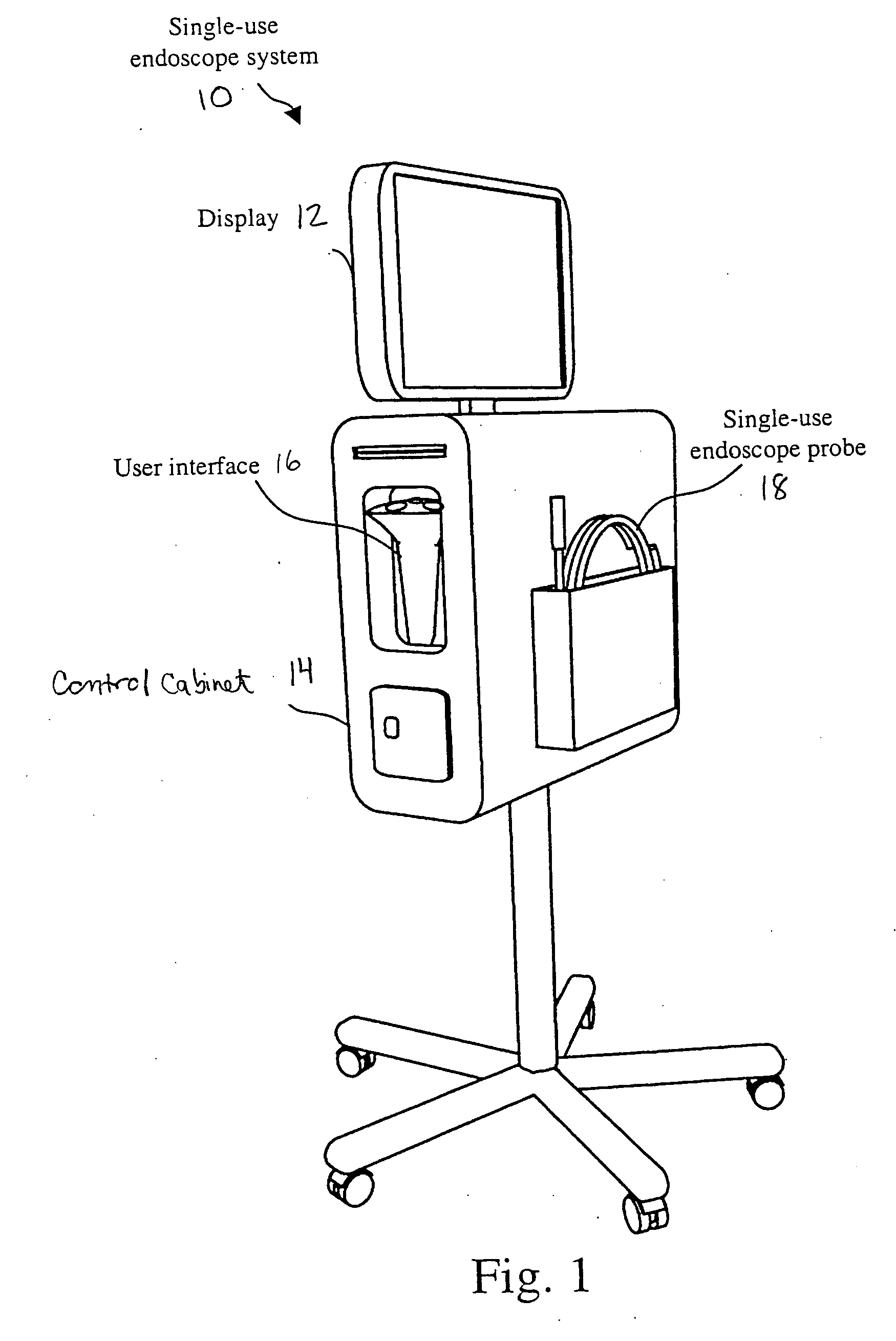
[0015]FIG. 1 illustrates the major components of an exemplary single-use endoscopic imaging system 10. The components of the system 10 include a display 12, a user input device 16, and a single-use imaging endoscope 18, all of which are functionally connected to a control cabinet 14 that executes application software (not shown) residing therein. Display 12 is any special-purpose or conventional computer display device, such as a computer monitor, that outputs graphical images and / or text to a user. Single-use imaging endoscope 18 is a single-use flexible tube that contains one or more lumens for the purpose of ...


PUM


Abstract

An endoscopic imaging system for examining a patient's body cavity includes an endoscope having a distal end, a proximal end and a number of lumens therein. One or more distal gas ports are disposed at or adjacent the distal end of the endoscope and one or more proximal gas ports are disposed proximal to the distal gas ports. Insufflation gas is delivered to the distal gas ports and withdrawn from the proximal gas ports or vice versa such that a gas bubble is formed in the body cavity and travels with the distal tip of the endoscope.

Description

FIELD OF THE INVENTION [0001] The present invention relates to an automatic medical insufflation device for diagnostic and surgical endoscopy. In particular, it relates to a system for and method of creating and controlling an observation space within a human body cavity so as to optimize diagnostic and / or surgical endoscopy by insufflation. BACKGROUND OF THE INVENTION [0002] Endoscopes have been used in the medical field for many years to look within a selected region of a patient's body, e.g., the colon. The endoscope is typically inserted through an orifice or a surgical incision into a body channel or cavity. Endoscopes are commonly used to perform surgical, therapeutic, diagnostic, or other medical procedures under direct visualization. Conventional endoscopes generally contain several endoscope components, including illuminating means such as light-emitting diodes or fiber optic light guides connected to a proximal source of light, imaging means such as a miniature video camer...

Claims


Application Information

Patent Timeline
Patent Type & Authority Applications(United States)
IPC IPC(8): A61B1/015
CPCA61B1/00094A61B1/31A61B1/051A61B1/015A61B1/00101
Inventor BANIK, MICHAEL S.COUVILLON, LUCIEN ALFRED JR.BOULAIS, DENNIS R.NGUYEN, ANH
Owner BOSTON SCI SCIMED INC
Why Eureka
Try Eureka