We have discovered a ureteral
stent design that avoids patient discomfort and urine
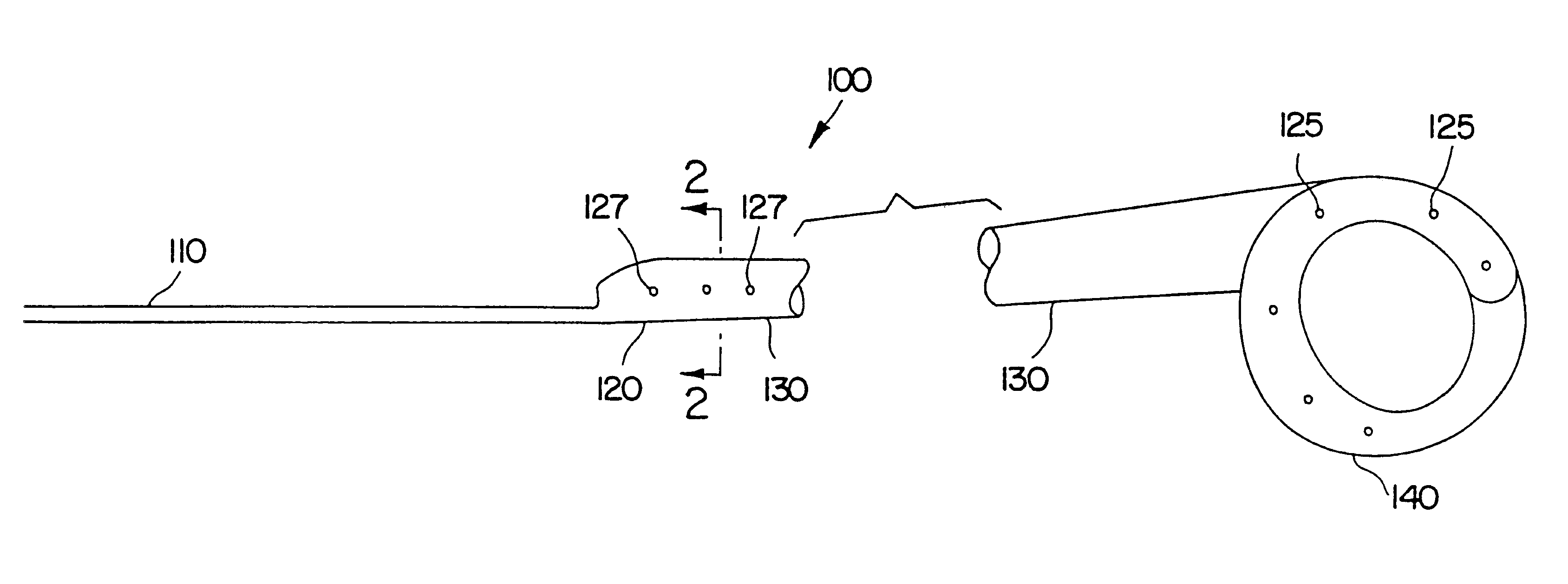
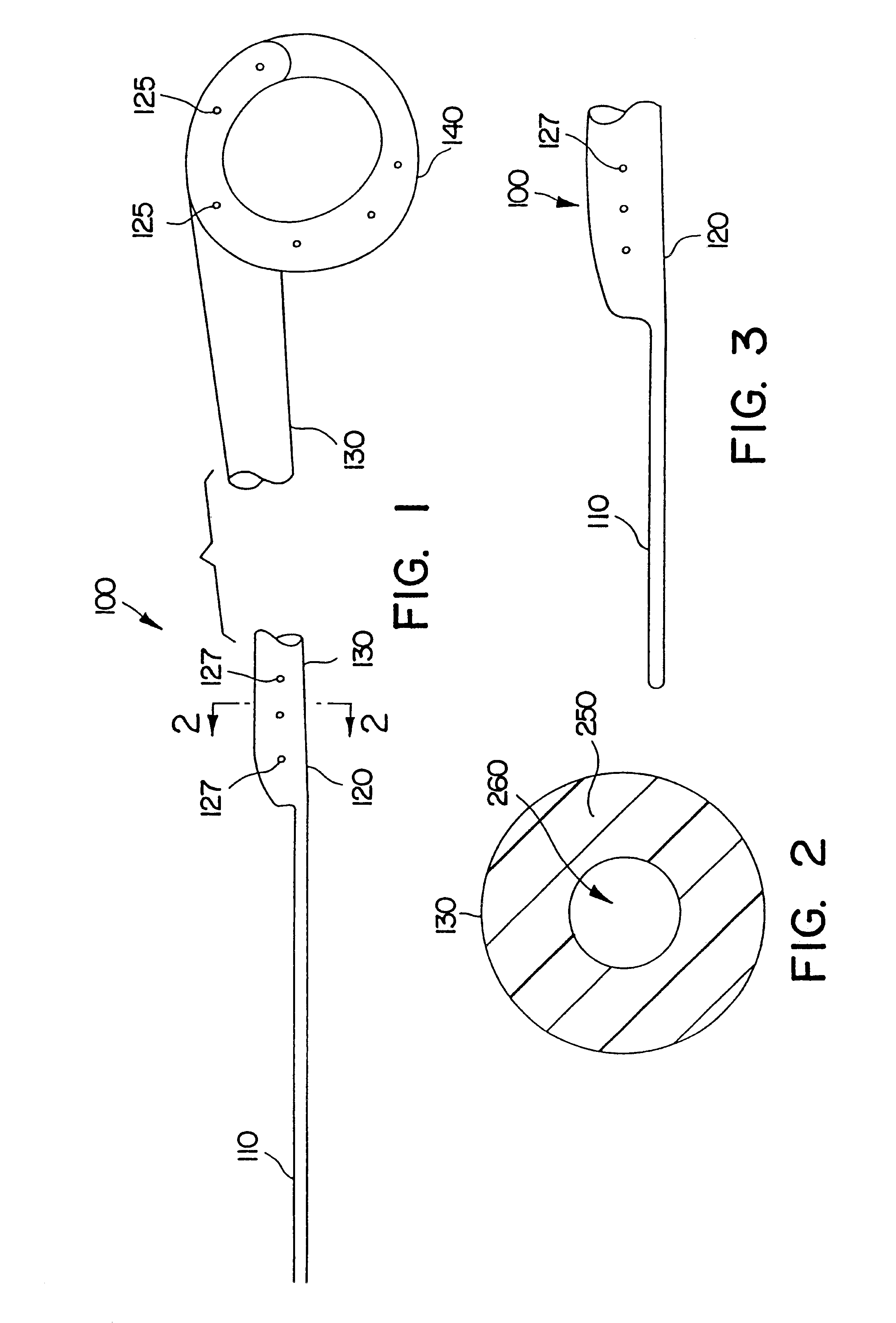
reflux upward toward the kidney. Rather than rely on a tubular structure to contain and facilitate all (or, in some embodiments, any)
urine flow along the ureter, the invention features a thin flexible elongated
tail member having an elongated external urine-transport surface.
Urine flows along the outside surface of the structure, between that surface and the inside wall of the ureter. Without limiting ourselves to a specific mechanism, it appears that urine may remain attached to, and flow along, the external urine transport surface. The use of a
foreign body that is as small as possible in the lower (bladder) end of the ureter and in the bladder itself decreases patient discomfort. Typically, the external urine transport surface is sized and configured to extend along at least part of the ureter near the bladder, across the ureter / bladder junction, and from there through the ureteral opening into the bladder.
Typically the elongated
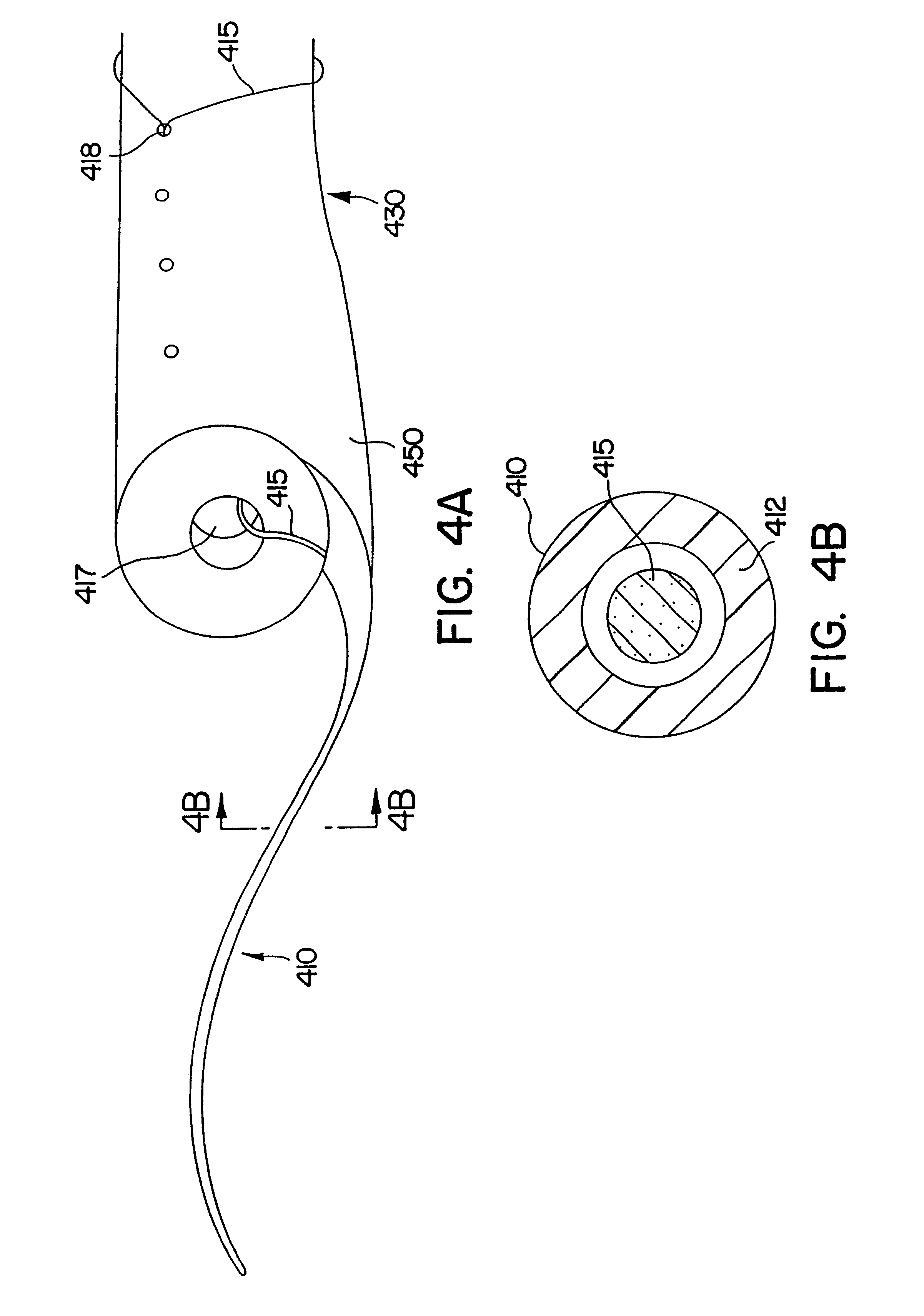
tail member comprises at least one (and more preferably at least two) thread filament(s). Two or more of the filaments may be configured in at least one filament loop, and, advantageously, the tail comprises no unlooped filaments, so that the tail is free from loose ends. The loop(s) can be made by joining the ends of a
single filament, in which case the filament loop comprises a junction of individual filament ends, which junction typically is positioned at the point where tail joins to the elongated tubular segment. Preferably, the tail is long enough to effectively prevent migration of the entire tail into the ureter, and the tail has a smaller outer
diameter than the outer
diameter of the tubular segment.
The tubular stent segment is stiff enough to avoid crimping during
insertion through the ureter, so that it can be inserted by typical procedures. The tail, on the other hand, is extremely flexible (soft) in comparison to the tubular segment, and it has a much smaller
diameter than the tubular segment to avoid discomfort. Even quite thin structures will provide urine transport, and the thinner and more flexible the tail is, the less likely it is to cause patient discomfort. On the other hand, the tail (and its connection to the rest of the stent) should have sufficient strength so the stent can be retrieved by locating the tail in the bladder and pulling on the tail to retrieve the stent from the kidney and ureter. Details of the tail size are discussed below. The use of reinforcing materials (e.g., sutures as described below) permits the use of thinner tails while still providing the ability to locate the tail in the bladder and to retrieve the stent. The tail may be a suture, and the suture may be coated to avoid encrusting.
To make the stent, the tail may be molded in one piece with the tubular segment, or it may be made separately and attached to the bladder end region of the tubular segment at a point toward the kidney from the bladder end of the lower region of the tubular segment. In one specific embodiment, the tail is attached near or at the bladder end of the bladder end region of the tubular segment. The stent may include a suture securing the tail to the tubular segment, and the suture may be incorporated into the tail to impart strength to the tail so the tail may be used to retrieve the stent. If the tail includes a hollow lumen, the suture may be positioned inside that lumen. The suture may be attached to the tubular segment at a point in the bladder end region of the tubular segment, and the suture may extend from the point of attachment through an opening in the bladder end region to the central lumen of the tubular segment and from there to the hollow tail. Alternatively, at least the bladder end region of the tubular segment may include two lumens, a main urine-transporting lumen and a bladder lumen to encase the suture, so that the suture does not become encrusted.
The use of relatively thin, flexible elongated member(s) to assist
urine flow across the ureterovesical junction and into the bladder may reduce
reflux and
irritation and thereby reduce patient discomfort and medical problems associated with
ureteral stents.

