Thoracic catheter device

a catheter and thoracic technology, applied in the field of thoracic catheters, can solve the problems of thoracic catheter, obstruction or blockage, and the ideal functioning design of the device has been so far stubbornly elusive, and achieve the effect of reducing patient discomfor

Active Publication Date: 2019-08-13
BOARD OF SUPERVISORS OF LOUISIANA STATE UNIV & AGRI & MECHANICAL COLLEGE
View PDF10 Cites 0 Cited by
  • Summary
  • Abstract
  • Description
  • Claims
  • Application Information

AI Technical Summary

Benefits of technology

[0015]Among the many advantages of the disclosed novel design is the ability to directly visualize a clot or an impedance to flow in a thoracic catheter, which as described above, is a common, recognized, and unresolved problem with the day-to-day management in patients with thoracic catheters. With the disclosed device, a physician can directly visualize any blockage and intervene through irrigation and suction. Additionally, as noted above, this device could act as an entry port for video assisted thoracoscopy surgery. Standard video-assisted thoracoscopy surgery requires three or more ports. This single port option would dramatically decrease patient discomfort and medical and surgical complications.
[0016]Additionally, a novel method and device for clearing the catheter of blockage is envisioned. A clearing component of known length is inserted into the catheter to scrape the interior walls of the catheter or otherwise clear the catheter of blockage, preferably with a slight to moderate concurrent negative pressure applied. The head of the clearing component may be, for example, bristle, screw, and / or rotary blade shaped, and will preferably rotate as it is inserted into the catheter. The head will be connected and supported by a flexible linear support body. In a preferred embodiment, the screw or cutting angled component head will preferably, as it rotates, pull the blockage in a direction towards the proximate end of the catheter upon encountering the blockage, whereby the negative pressure will also aid in moving the blockage and any debris out of the catheter and away from the patient. Additionally or alternatively, the head of the cleaning component could have an extendable clasp that grabs hold of the blockage and allows the blockage to be pulled or pulled and / or suctioned out.

Problems solved by technology

Despite the fact that thoracic catheters are used quite commonly worldwide, an ideal functioning design for the device has proven thus far stubbornly elusive, regardless of the significant market forces motivating such an improvement.
The most frequent complication associated with a thoracic catheter is clogging or blockage of the catheter lumen by thrombus formation or debris that is inside the catheter lumen.
This clogging can cause major subsequent complications and non-functioning or malfunctioning of the tube.
The presence of a clot inside the catheter lumen can also cause stasis of the drainage, cause infections and / or deterioration of infections (e.g., in cases with empyema).
Such clogging was also associated with a higher risk of atrial fibrillation development in the patient, which could potentially be a lethal complication.
Interestingly, more than eighty percent of the clogging in the thoracic catheter was found to be in the internal portion of the tube (i.e., the non-visible or intra-thoracic portion that is inside the patient's chest cavity), which makes the diagnosis of this complication by bedside visualization and or inspection very difficult or impossible.
Due to the same reason, management of this complication can be complex and challenging.
The thoracic catheter can become clogged at any time after its placement, and it is known that clinicians generally underestimate the prevalence of this failure to drain.
Clogging of the tube can even become life threatening in cases where bleeding in the chest goes undiagnosed due to lack of drainage.
In case of the pneumothorax, blockage in the thoracic catheter can cause tension pneumothorax, which is life threatening.
In addition, the survey respondents noted that patients experience increasing discomfort with increasing drain size and did not think that increasing the size of the thoracic catheters was a good strategy to prevent clogging of the tubes.
Another challenge with the current thoracic drainage system is when a patient who already has a thoracic catheter in place requires a video-assisted thoracoscopic surgery (“VATS”) procedure.
Outside experts in the field of thoracic catheters have expressed skepticism of single incision VATS due to current technological limitations.

Method used


Image

  • Thoracic catheter device
  • Thoracic catheter device
  • Thoracic catheter device

Examples


first embodiment

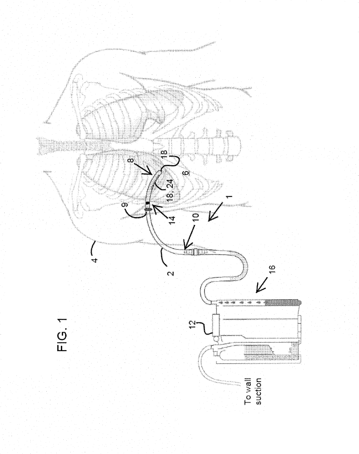
[0033]Turning now to FIG. 1, a brief description concerning the various components of the present invention will now be briefly discussed. As can be seen in this first embodiment, the invention is a thoracic catheter system 1 comprising a flexible or semi-flexible chest tube or thoracic catheter 2 made from plastic, silicone, rubber, metal, or some combination thereof. A distal end 4 of the thoracic catheter 2 is inserted into the thoracic cavity 6 of the patient 8 through an incision 9, and a proximate end 10 of the thoracic catheter 2 is connected to a suction canister 12 or wall or other suction. The thoracic catheter 2 will preferably include special internal coatings, such as, inter alia, polytetrafluoroethylene (“Teflon”), Tethered-Liquid Perfluorocarbon (comprising a monolayer of perfluorocarbon and a layer of liquid perfluorocarbon), silver ionic, silver nanoparticles, copper, copper alloy, organosilanes, gold, titanium dioxide, and carbon nanotubes, to help prevent clot or ...

second embodiment

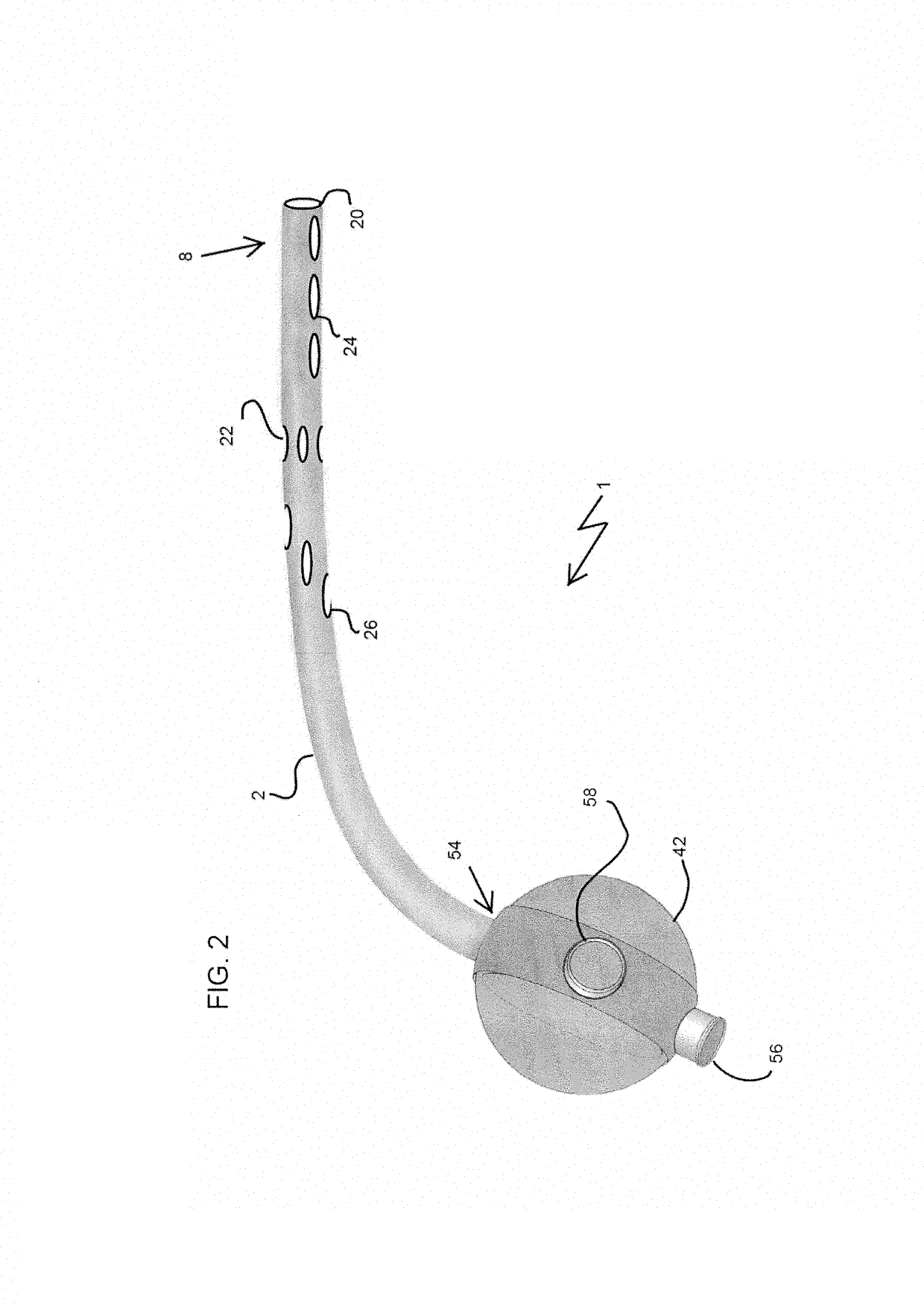
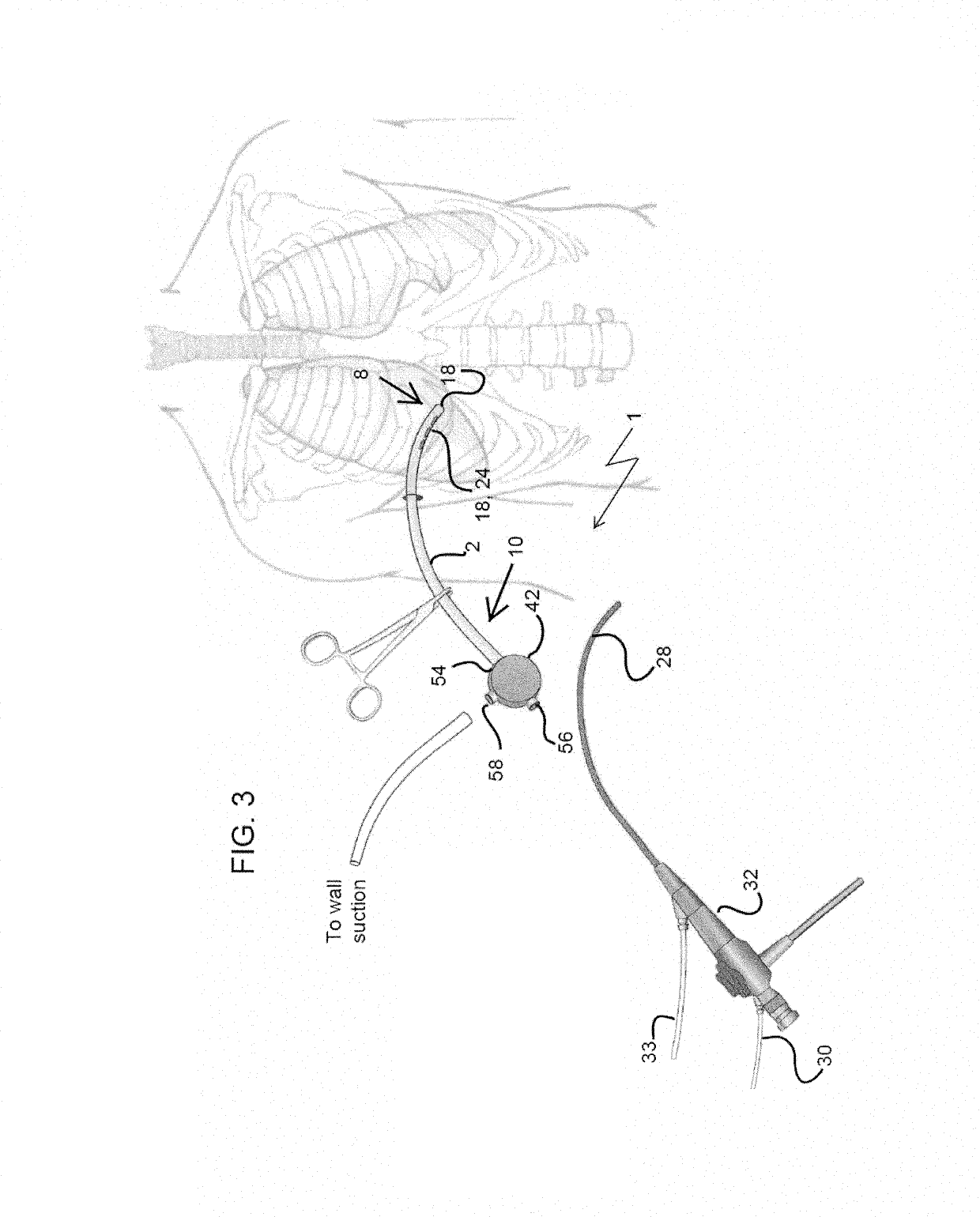
[0036]the thoracic catheter system 1, as shown in FIG. 2, includes a three way valve 42 which is one of fused / permanently attached and removably attached to the outer proximate end 10 of the thoracic catheter 2.

[0037]One embodiment of the three way valve or medical stopcock 42 consists of a chamber part or hollow body 44, with three through holes 46 of preferably equal diameter at 90° degree intervals along a circumference of the hollow body 44. While the hollow body 44 is shown in the shape of a sphere, it may also have the shape of an oblate spheroid, a prolate spheroid or a cylinder, for example. An inner surface of the hollow body 44 is preferably a smooth sphere, spheroid, or cylinder, except for the through holes 46 extending through the wall of the hollow body 44. An outer ring 48 with the external ports 50 is placed around the hollow body 44 perimeter. The outer ring 48 can be rotated around the hollow body 44, or, conversely, the hollow body 44 can be rotated within the out...


PUM


Abstract

A thoracic catheter system comprises a flexible thoracic catheter for inserting into a thoracic cavity of a human. A distal end of the thoracic catheter has a plurality of apertures. A proximate end of the thoracic catheter is designed to extend out of the thoracic cavity. A three way valve is one of fused with and removably attached to the proximal end of the thoracic catheter.

Description

CROSS REFERENCE TO RELATED APPLICATIONS[0001]This application claims priority to U.S. Provisional Patent Application No. 62 / 072,075 filed Oct. 29, 2014, the contents of which are incorporated herein by reference in its entirety.STATEMENT REGARDING FEDERALLY SPONSORED RESEARCH OR DEVELOPMENT[0002]Not applicable.FIELD OF THE INVENTION[0003]The present invention generally relates to thoracic catheters. The present invention further relates to medical imaging, drug delivery, and fluid control devices.BACKGROUND OF THE INVENTION[0004]The use of thoracic catheters (also referred to as a chest drain, chest tube, intercostal drain, tube and tube thoracostomy) is widely known, and became popular after the widespread use during the World War II and the Korean War. A thoracic catheter is known as a flexible / semi-flexible tube which is inserted into the chest cavity (pleural and / or pericardial space) and is used to remove / evacuate air (pneumothorax) or fluids (blood, effusion, chyle or pus) fro...

Claims


Application Information

Patent Timeline
Patent Type & Authority Patents(United States)
IPC IPC(8): A61M1/00A61M25/00A61M27/00
CPCA61M1/008A61M1/0001A61M25/0068A61M2210/101A61M27/002A61M1/84A61M1/66
Inventor HAMIDIAN JAHROMI, ALIREZABALLARD, DAVID HILTONWEISMAN, JEFFERY ADAMD'AGOSTINO, HORACIO RUBEN VINCENT
Owner BOARD OF SUPERVISORS OF LOUISIANA STATE UNIV & AGRI & MECHANICAL COLLEGE
Why Eureka
Try Eureka