Al technical title is built by PatSnap Al team. It summarizes the technical point description of the patent document.
a ureteral stent and patient technology, applied in the direction of wound drains, prostheses, catheters, etc., can solve the problems and achieve the effect of reducing patient discomfort and medical problems, reducing reflux and irritation
Inactive Publication Date: 2006-01-31
BOSTON SCI SCIMED INC
View PDF388 Cites 29 Cited by
Summary
Abstract
Description
Claims
Application Information
AI Technical Summary
This helps you quickly interpret patents by identifying the three key elements:
Problems solved by technology
Method used
Benefits of technology
[0027]The use of relatively thin, flexible elongated member(s) or filament(s) to assist urine flow across the uretero-vesical junction and into the bladder may reduce reflux and irritation, thereby reducing patient discomfort and medical problems associated with other types of ureteral stents.
Problems solved by technology
The use of a foreign body that is as small as possible in the lower (bladder) end of the ureter and in the bladder itself decreases patient discomfort.
Method used
Image
Click on the blue label to locate the original text in one second.
Reading with bidirectional positioning of images and text.
Examples
Embodiment Construction
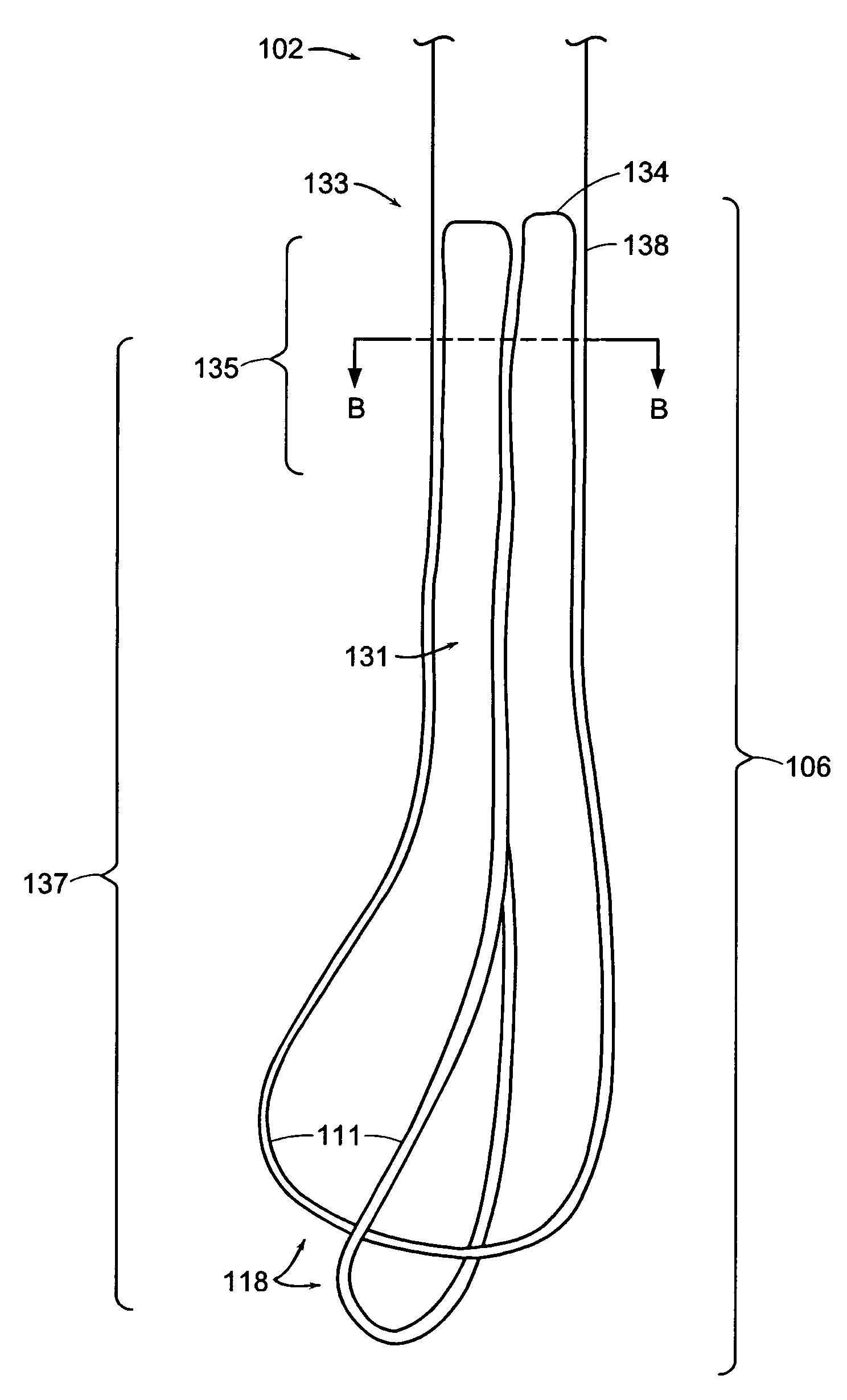
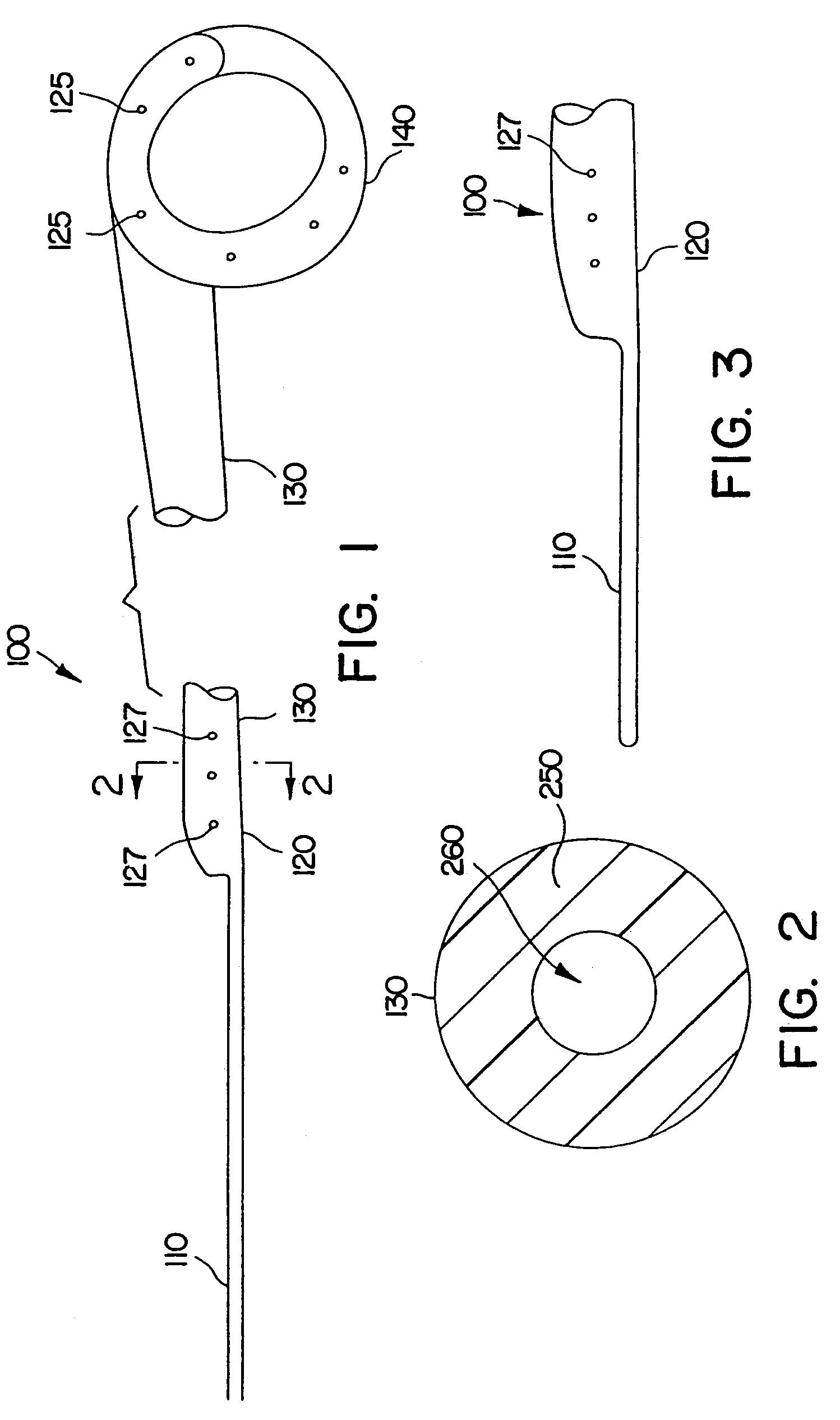
[0048]In FIG. 1, ureteral stent 100 includes an elongated tubular body 130 connecting coil end 140 to straight end region 120. Tubular body 130 is designed to extend from the renal pelvis through the ureter to a terminus upstream of the bladder. Tail 110 is attached to straight end region 120, and tail 110 extends along the ureter, across the ureter / bladder junction and into the bladder.
[0049]The two opposing end regions 120 and 140 of elongated tubular body 130 are illustrated in FIG. 1. Coiled end region 140 is designed to be placed in the renal pelvis of the kidney. For illustrative purposes, coiled end region 140 is shown with a pigtail helical coil although any shape that will retain the stent in place within the kidney will do. Coiled end region 140 includes several openings 125 placed along the wall of the tubular body; the openings may be arranged in various geometries (e.g., axial, circumferential, spiral). The entire tubular segment, including the region between the kidney...
PUM
Property
Measurement
Unit
outer diameter
aaaaa
aaaaa
length
aaaaa
aaaaa
length
aaaaa
aaaaa
Abstract
A ureteral stent for assisting the movement of urine along a patient's ureter and into the patient's bladder. The stent includes an elongated tubular segment extending toward the bladder from a kidney end region for placement in the renal cavity to a bladder end region. A central lumen connects at least one opening at the first end region to at least one opening in the bladder end region. Thin flexible tail(s) are attached to the bladder end region of the tubular segment at a point outside the bladder so as to receive urine from the opening in the bladder end region of the tubular segment and to transport urine from there across the ureter/bladder junction and into the bladder. The tails include an elongated external urine-transport surface sized and configured to transport urine along the ureter. The urine transporting surface(s) are sized and configured to extend along at least part of the ureter, across the ureter/bladder junction, and from there into the bladder. In some embodiments, the distal region includes a tubular body with a lumen in fluid communication with an interstitial area defined by one or more flexible filaments of the proximal region forming at least one loop.
Description
RELATED APPLICATIONS[0001]This application is a continuation-in-part of U.S. patent application Ser. No. 09 / 300,657, filed on Apr. 27, 1999, now U.S. Pat. No. 6,656,146 which is a continuation of U.S. Ser. No. 08 / 743,885, filed on Nov. 6, 1996, now U.S. Pat. No. 6,849,069 which claims priority to and the benefit of U.S. Provisional Patent Application Ser. No. 60 / 006,259 filed Nov. 7, 1995, U.S. Provisional Patent Application Ser. No. 60 / 009,983 filed Jan. 16, 1996, and U.S. Provisional Patent Application Ser. No. 60 / 025,284 filed Sep. 19, 1996. This application is also a continuation-in-part of U.S. patent application Ser. No. 09 / 849,202, filed May 4, 2001 now U.S. Pat. No. 6,676,623. The contents of each of these applications are incorporated herein by reference.TECHNICAL FIELD[0002]This application relates generally to medical devices for drainage of fluids, and more specifically to ureteral stents.BACKGROUND[0003]Ureteral stents are used to assist urinary drainage from the kidney...
Claims
Application Information
Patent Timeline
Application Date:The date an application was filed.
Publication Date:The date a patent or application was officially published.
First Publication Date:The earliest publication date of a patent with the same application number.
Issue Date:Publication date of the patent grant document.
PCT Entry Date:The Entry date of PCT National Phase.
Estimated Expiry Date:The statutory expiry date of a patent right according to the Patent Law, and it is the longest term of protection that the patent right can achieve without the termination of the patent right due to other reasons(Term extension factor has been taken into account ).
Invalid Date:Actual expiry date is based on effective date or publication date of legal transaction data of invalid patent.