Machine vision system for lab workcells

a lab workcell and machine vision technology, applied in the field of laboratory automation systems, can solve the problems of cumbersome operation, affecting the operation efficiency of the robot, and becoming a tedious task

Inactive Publication Date: 2006-03-02
HUDSON CONTROL GROUP
View PDF11 Cites 36 Cited by
  • Summary
  • Abstract
  • Description
  • Claims
  • Application Information

AI Technical Summary

Benefits of technology

[0014] The invention relates to a system for learning specimen holder locations in a work cell of a laboratory for automated handling of specimen holders. In one embodiment of the system, a robotic manipulator is adapted for automated manipulation of a specimen holder. The robotic manipulator preferably has a plurality of ranges of motion for retrieving or depositing a specimen holder at a plurality of positions in equipment of the work cell of the robotic manipulator. One or more teaching targets or teaching plates may be adapted to represent a specimen holder for placement in the equipment of the work cell. The teaching device is adapted for providing visual information to a vision feedback control system. The vision feedback control apparatus coupled with the robotic manipulator controls the plurality of ranges of motion of the robotic manipulator in response to detecting the visual information of the teaching plate to automatically position the robotic manipulator to an orientation adjacent to the teaching plate. The vision feedback control apparatus is also configured for storing positioning information of the robotic manipulator for retrieving or depositing a specimen holder at a location represented by the teaching plate. A stored coordinate controller also automatically controls returning the robotic manipulator to an orientation represented by the stored positioning information previously determined by the vision feedback control apparatus in conjunction with locating a teaching plate.

Problems solved by technology

This can become a tedious task if large numbers of plates need to be processed.
However, even with such “walkaway automation” since most of these processes require several instruments, there is often some degree of manual movement of microplates from one instrument to another as the chain of required events is processed.
Stacker devices work well but are limited in functionality to feeding plates to a single instrument.
Articulated arms can offer a good degree of capability, but are more cumbersome to set up and operate, and are often more expensive.
Linear track robotic arms can be very powerful within large scale automated systems, but these solutions are very expensive and often require long lead times to install or modify if new configurations are desired.
However, with increased functionality comes increased complexity.
The time taken for such a process is further complicated considering that robotic apparatus may have several axis of control that need to be manipulated in order to move the gripper to each location.

Method used


Image

  • Machine vision system for lab workcells
  • Machine vision system for lab workcells
  • Machine vision system for lab workcells

Examples


Embodiment Construction

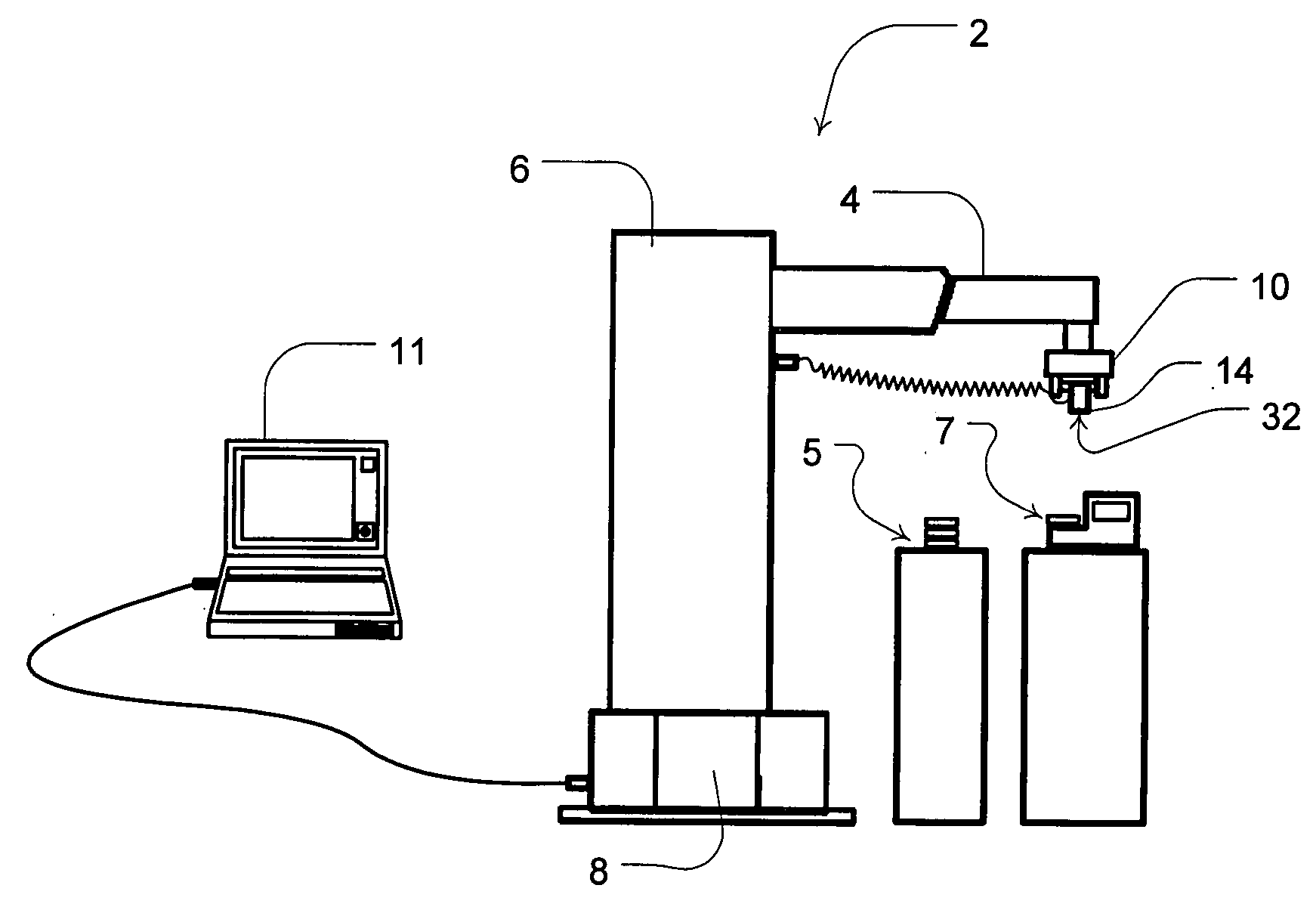
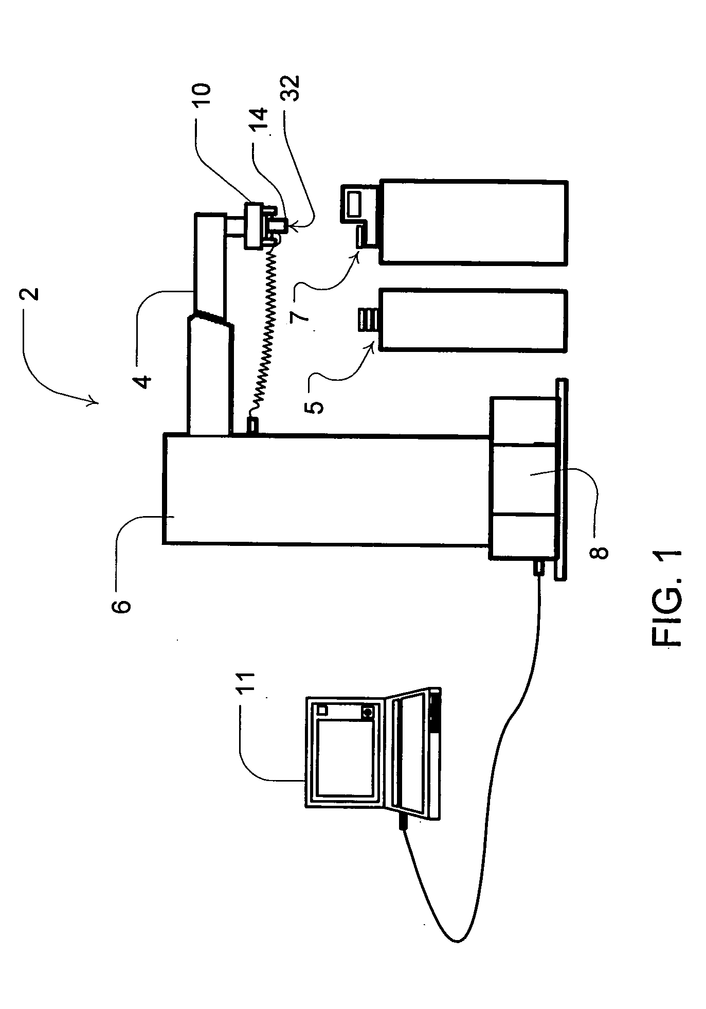
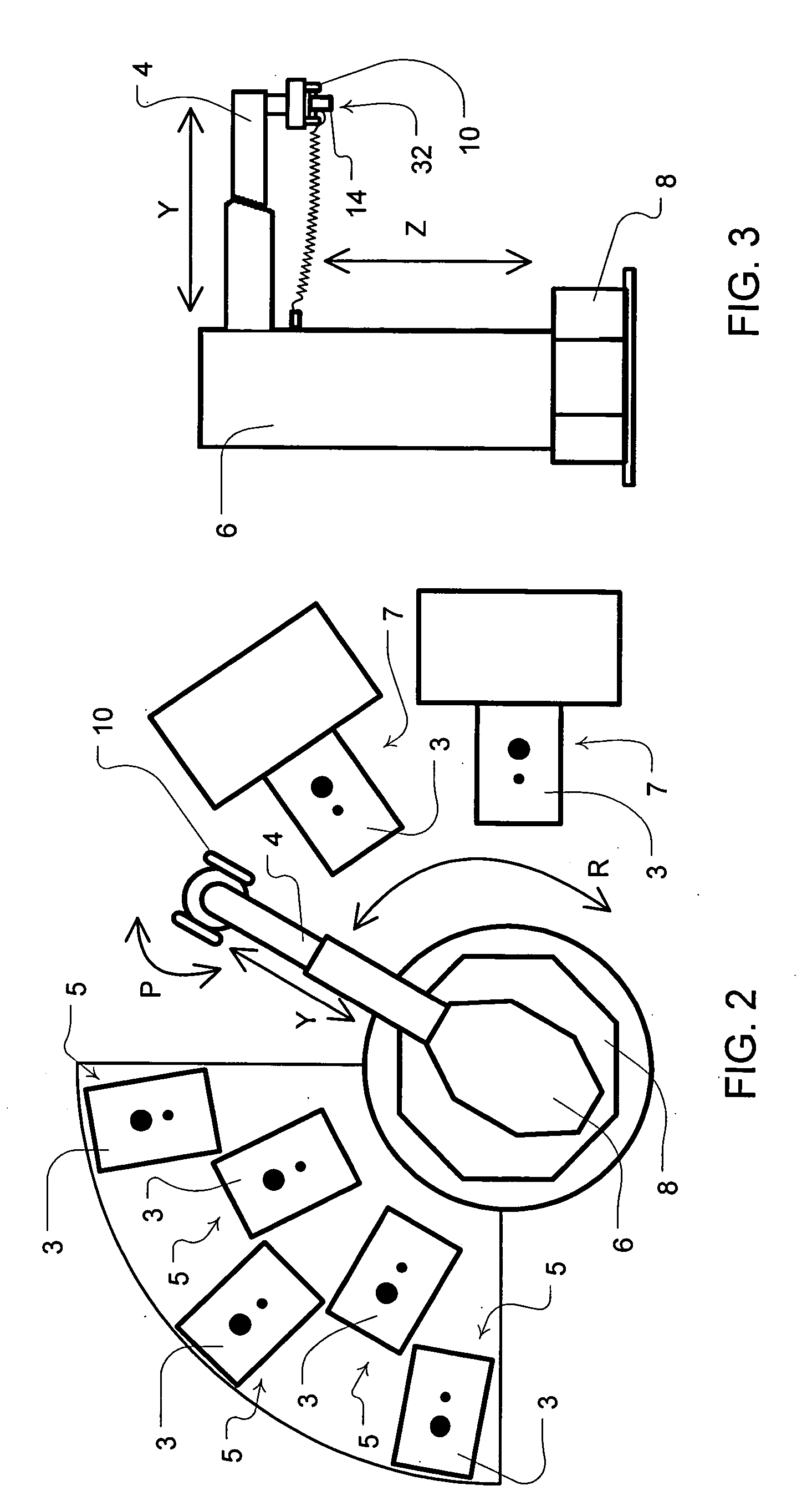
[0028] Referring to the figures, where like numerals indicate similar features, a laboratory automation system of the invention includes a robotic manipulator 2 adapted for automated manipulation of a laboratory specimen or sample holder such as a microplate. For example, as illustrated in FIGS. 1-3, the preferred robotic manipulator 2 is a cylindrical robot. However, the robotic manipulator may alternatively include other robotic automation devices such as an articulated arm or SCARA arm.

[0029] The preferred cylindrical robot includes an arm 4, a tower 6, a base 8, a gripper 10, a controller 12 and an imaging device 14. As will be explained in more detail, the robot with the equipped imaging device 14 can home in on a target or a common pattern on multiple teaching plates, and identify and store each specimen holder position in a laboratory work cell associated with the teaching plates for later automated handling.

[0030] To these ends, the robotic manipulator 2 is preferably conf...


PUM


Abstract

A robotic laboratory automation system includes a vision feedback apparatus with one or more teaching plates adapted for placement in a microplate or other specimen holder of a laboratory instrument or stack to represent the location of the microplate. The vision feedback system is adapted to control the robotic manipulator to automatically adjust the location of the manipulator to a position adjacent to a teaching plate upon locating a pattern on the teaching plate and then store the coordinates of the determined position. With the stored position coordinates the robot can return to the determined positions previously represented by the location of teaching plates to locate an actual microplate or specimen holder at the determined position without the vision feedback system.

Description

CROSS REFERENCE TO RELATED APPLICATIONS [0001] This application claims the benefit of the filing date of U.S. Provisional Patent Application No. 60 / 605,790 filed Aug. 31, 2004 (attorney reference number HUDCON 3.8-001), the disclosure of which is hereby incorporated herein by reference.FIELD OF THE INVENTION [0002] The present invention relates to laboratory automation systems. More particularly, the invention involves a laboratory work cell robot configured for vision navigation for learning workcell positions for automating microplate manipulation in the workcell. BACKGROUND OF THE INVENTION [0003] Pharmaceutical and biotechnology companies produce and work with larger and larger numbers of compounds and processes, sometimes numbering in the millions. Such applied processes may involve, for example, drug discovery, high throughput screening, genomics, and proteomics. Many of such processes (although not all) revolve around the use of samples within the microplate format. The micro...

Claims


Application Information

Patent Timeline
Patent Type & Authority Applications(United States)
IPC IPC(8): G06F19/00
CPCG01N35/00722G01N35/0099G05B2219/37067B25J9/1692G01N2035/0491
Inventor FARRELLY, PHILIP J.BARTOLETT, SCOTT
Owner HUDSON CONTROL GROUP
Why Eureka
Try Eureka