
Electrically-driven tape cutter

a tape cutter and electric drive technology, applied in the direction of metal working apparatus, thin material handling, article delivery, etc., can solve the problems of overall apparatus noise production, overall apparatus malfunction,

Inactive Publication Date: 2006-03-09
KTF
View PDF5 Cites 1 Cited by
  • Summary
  • Abstract
  • Description
  • Claims
  • Application Information

AI Technical Summary

Benefits of technology

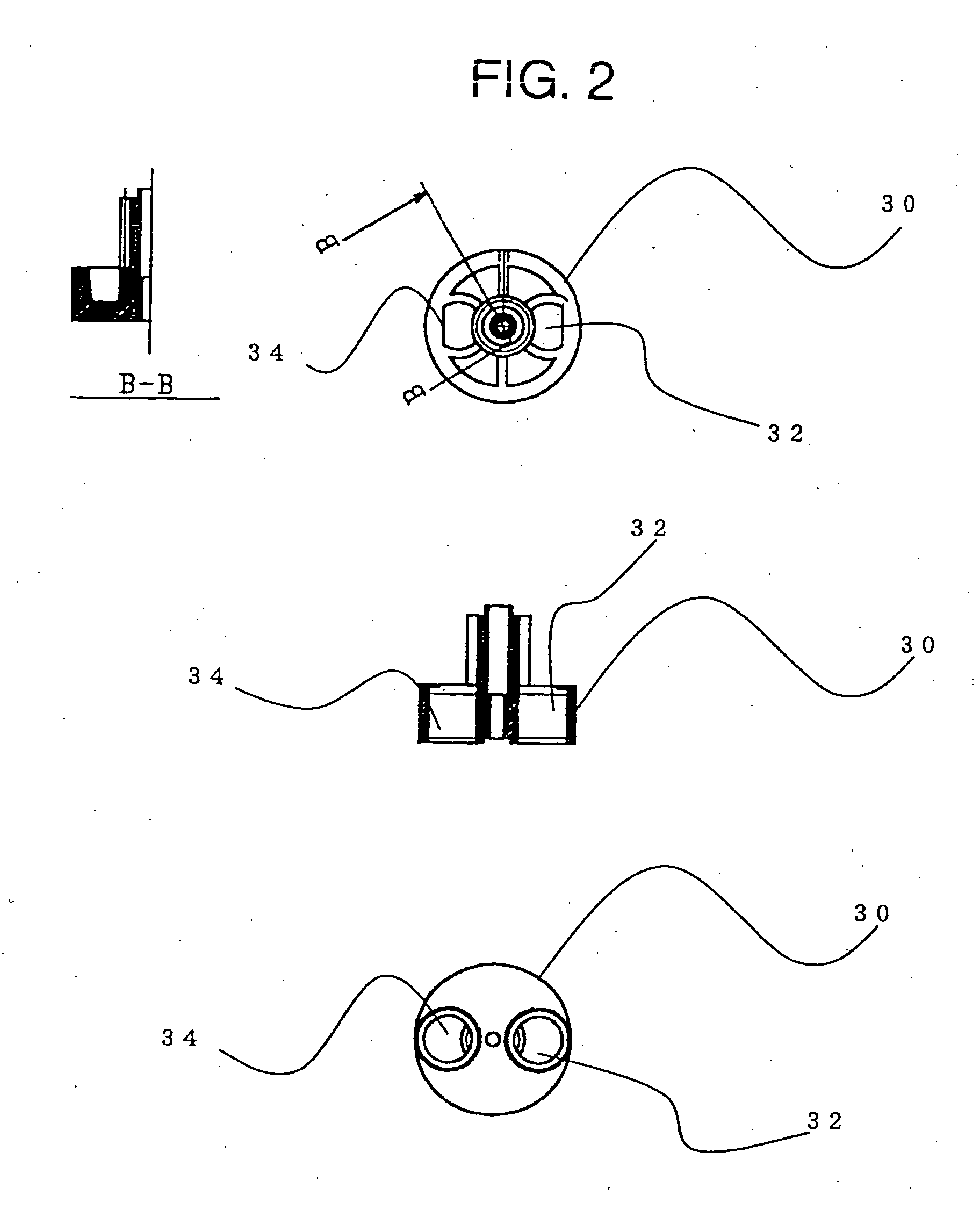
[0009] To attain the above object, this invention provides an electric tape cutter that feeds a leading edge of adhesive tape wound on a reel from a delivery outlet and cuts it to an appropriate length with an electrically driven blade provided at the delivery outlet, wherein in order to prevent eccentric rotation of a pinion gear that has a magnet affixed thereto and is connected to a drive source, a fitted member of equal weight to the magnet is embedded in the pinion gear at a location that is symmetrical to the position at which the magnet is provided, with the axis of rotation of the pinion gear therebetween. The object is also attained by an electric tape cutter in which the fitted member is composed of brass.

Problems solved by technology

However, because the magnet mounted on the pinion gear is embedded at one location on the pinion gear, rotation of the motor or the like that is the drive source becomes rotation that is off-center from the balanced weight.
An eccentrically rotating member mounted on the revolving shaft of a motor or the like gives rise to vibration and sounds, causing operation of the overall apparatus to produce noise.
Also, vibration caused by the eccentricity is transmitted to the overall apparatus, and use for an extended period of time can cause separation of the substrate pattern and, by extension, can cause malfunction of the overall apparatus.

Method used


Image

  • Electrically-driven tape cutter
  • Electrically-driven tape cutter
  • Electrically-driven tape cutter

Examples


Embodiment Construction

[0014] Details of the electric tape cutter of the invention will now be explained with reference to the drawings.

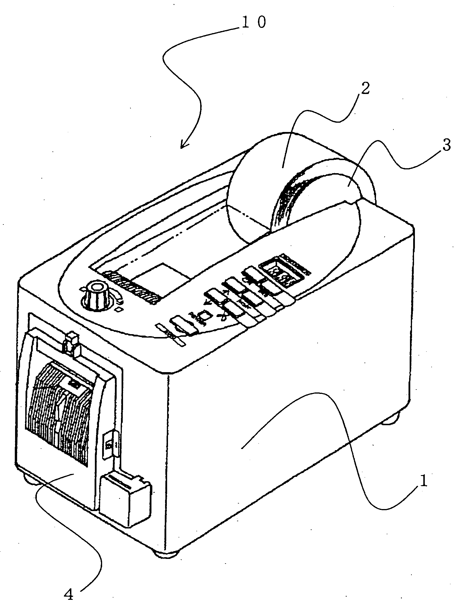
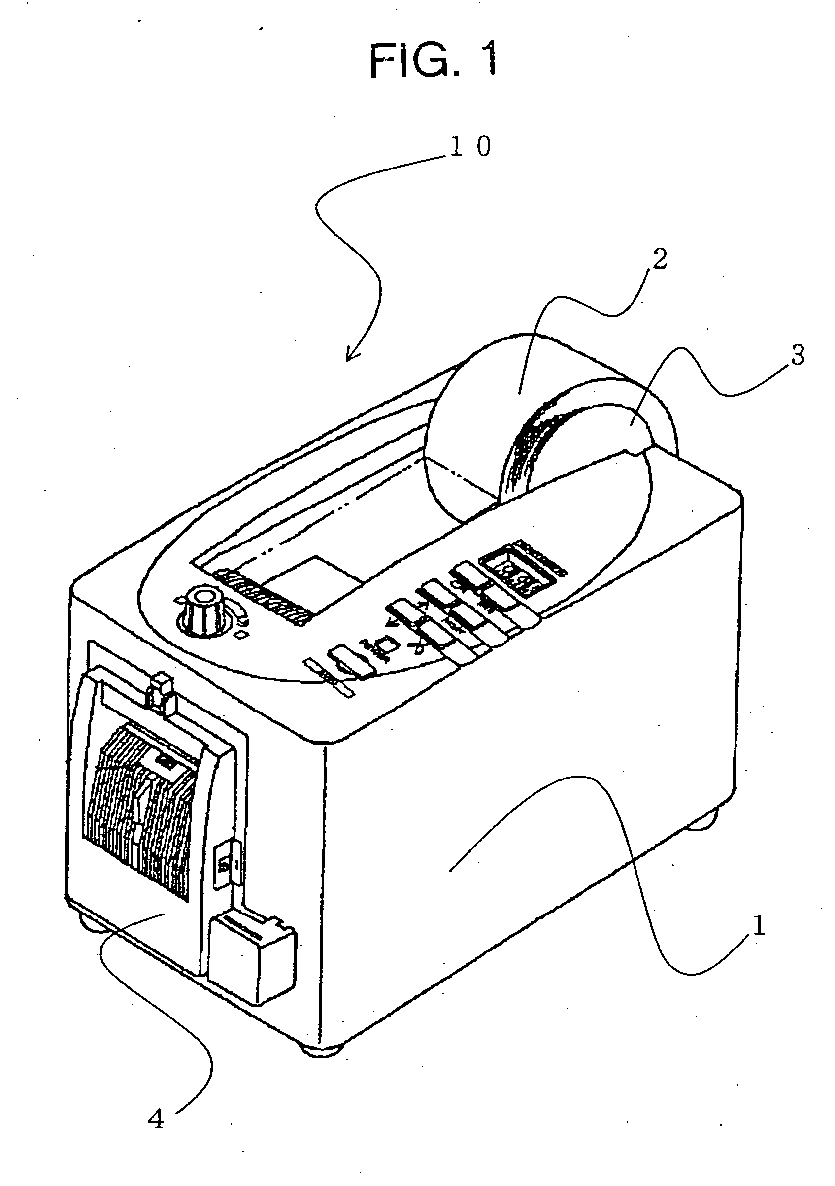
[0015] An electric tape cutter 10 according to the present invention comprises adhesive tape 2 wound on a reel 3, a drive unit 20 that feeds the tape from a delivery outlet, and a cutter unit (electrically driven blade) 4. The reel 3 on which the adhesive tape 2 is wound is mounted on the tape cutter body 1, and the drive unit 20 is operated to pay out the adhesive tape, which is automatically cut at a prescribed length by the cutter unit 4. This structure is the same as that of a conventional electric tape cutter.

[0016] In this embodiment, details will now be explained with respect to an improved pinion gear 30 for preventing noise, provided on the drive unit 20.

[0017] A control switch (not-shown) is used to supply electric power from a power supply to operate the drive unit 20 and feed out tape 2 from the reel 3. The drive unit 20 is equipped with a motor 22 that is ...


PUM

PropertyMeasurementUnit
lengthaaaaaaaaaa
weightaaaaaaaaaa
electric poweraaaaaaaaaa

Abstract

The invention provides an improved electric tape cutter in which a pinion gear with an attached magnet that is connected to a drive source is embedded with a member having a weight equal to that of the magnet at a location that is symmetrical to the location at which the magnet is mounted, with respect to a center axis of rotation, imparting balanced rotation that enables eccentric rotation of the pinion gear to be prevented, preventing noise and apparatus malfunction. The electric tape cutter, which feeds a leading edge of adhesive tape wound on a reel from a delivery outlet and cuts it to an appropriate length with an electrically driven blade provided at the delivery outlet, has a configuration wherein, in order to prevent eccentric rotation of a pinion gear that has a magnet affixed thereto and is connected to a drive source, a fitted member of equal weight to the magnet is embedded in the pinion gear at a location that is symmetrical to the position at which the magnet is provided, with the axis of rotation of the pinion gear therebetween.

Description

BACKGROUND OF THE INVENTION [0001] 1. Technical Field [0002] The present invention relates to an electric tape cutter that electrically drives adhesive tape wound on a reel to feed the tape from a delivery outlet and automatically cut it to an appropriate length. It particularly relates to an electric tape-cutter having a pinion gear to which a magnet is affixed connected to a drive source (motor) in which a fitted member having a weight equal to that of the magnet is embedded in the pinion gear at a position that is axially symmetrical to that of the magnet. [0003] 2. Description of the Prior Art [0004] Electric tape cutters in which adhesive tape wound on an annular member such as a reel or the like is fed out from a delivery outlet of a housing of a drive apparatus until a prescribed length is reached at which an electrically driven blade provided on the delivery outlet is operated to cut the tape are already known in, for example, Unexamined Patent Application Publication No. 6-...

Claims


Application Information

Patent Timeline
Patent Type & Authority Applications(United States)
IPC IPC(8): B26D1/00B65H35/00B65H35/07
CPCB65H35/0026B65H35/0066B65H2553/22B65H2403/40B65H2403/42B65H35/0086Y10T83/9447
Inventor ARAKI, HIROYUKI
Owner KTF
Learn More