
A Chip Breaking Structure of the Cutting Edge at the Variable Diameter Position of Step Drill

A cutting edge and step drill technology, which is used in step drills, components of boring machines/drilling machines, and drill repairs. Toughness and plasticity, the effect of avoiding scratches

Active Publication Date: 2020-08-04
DALIAN UNIV OF TECH +1
View PDF6 Cites 0 Cited by
  • Summary
  • Abstract
  • Description
  • Claims
  • Application Information

AI Technical Summary

Problems solved by technology

[0005] In order to overcome the defects of the prior art, the present invention solves the problems of continuous chips, scratches on the hole wall and entanglement of chips when the material is removed at the variable diameter position of the step drill.

Method used


Image

  • A Chip Breaking Structure of the Cutting Edge at the Variable Diameter Position of Step Drill
  • A Chip Breaking Structure of the Cutting Edge at the Variable Diameter Position of Step Drill

Examples


Embodiment Construction

[0012] The specific implementation manners of the present invention will be described in detail below in conjunction with the drawings and technical solutions.

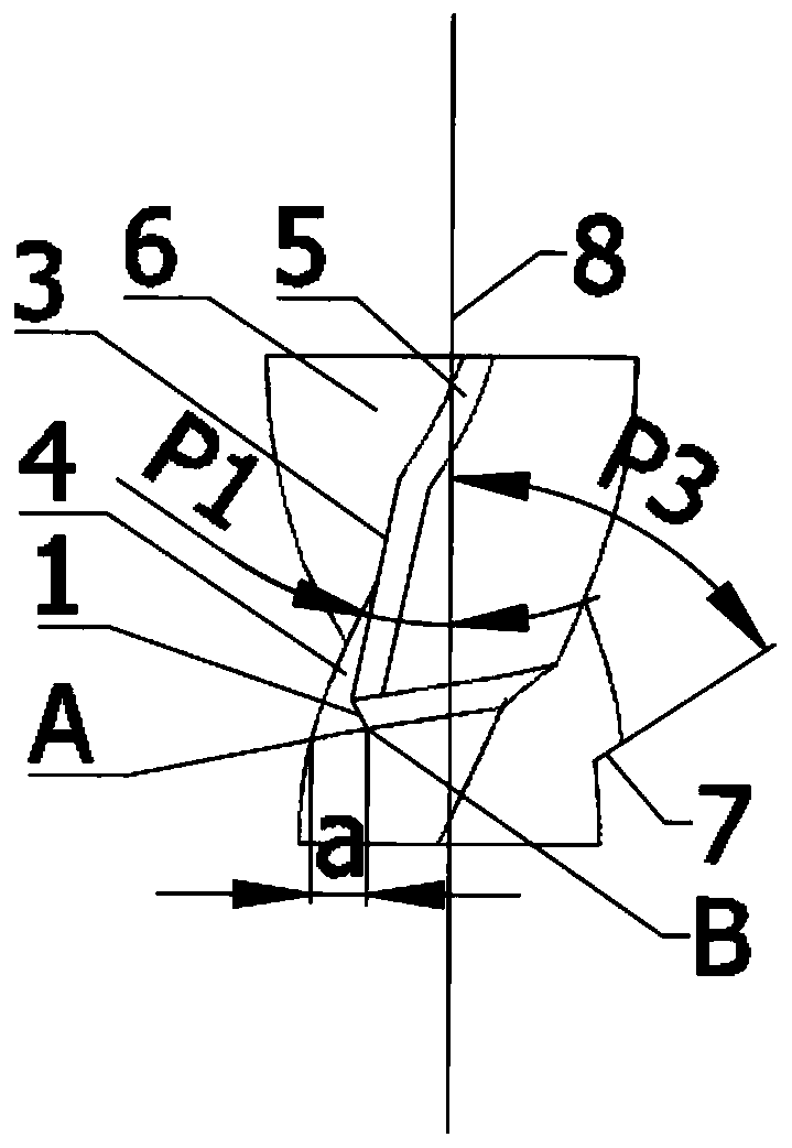
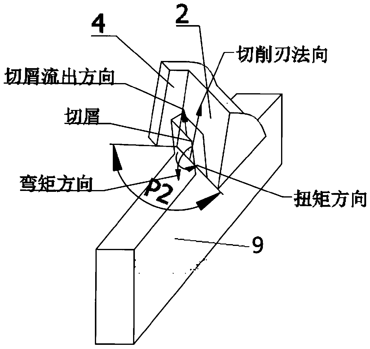
[0013] Such as figure 1 , figure 2 As shown, the present invention is a chip breaking structure of the cutting edge at the variable diameter position of the stepped drill. The chip flute 6 is formed by the end face 7 of the stepped rear section. This chip breaking structure changes the traditional continuous spiral edge cutting into step edge co-cutting, and the rake face also changes from an arc shape to an angled straight face to form a chip breaking space, and the angled rake faces make the chip break Bending and torsional deformation increase the chip stress, and it is easier to reach the breaking strength of the chip, effectively realizing metal chip breaking and debris.

[0014] Since CFRP is a complex mixture composed of fiber-reinforced phase and resin matrix phase, it has very different properties from ho...


PUM


Abstract

The invention belongs to the technical field of drilling tools in machining and relates to a chip breaking structure of a reducing position cutting edge of a stepped drill. The chip breaking structureis composed of a step reducing position cutting edge, a chip breaking cutter face, a chip breaking edge, a stop face, an edge strip, a chip discharging groove and a step back section end face. According to the chip breaking structure, traditional continuous spiral edge cutting is changed into step edge joint cutting, arc front cutter faces are changed into straight cutter faces mutually forming an angle, and a chip breaking space is formed. The front cutter faces mutually forming the angle enable cutting chips to bend and undergo torsional deformation, the stress of the cutting chips is increased, the breaking strength of the cutting chips is easier to reach, and therefore metal chip breaking and chip smashing are effectively achieved. The scratches, caused by continuous cutting chips, ofa hole wall are restrained, and cutter rotation deviation caused by twining of the cutting chips is reduced. The chip breaking structure facilitates to greatly improve the hole forming quality of thestep drill, reduces the machining cost and has good engineering application prospect.

Description

technical field [0001] The invention belongs to the technical field of drilling tools in mechanical processing, and relates to a chip breaking structure of a cutting edge at a variable diameter position of a step drill. Background technique [0002] In mechanical processing, it is often necessary to make a large number of holes on the components to complete the connection assembly by riveting, screwing and other methods. As the main hole-making tool, the drill bit directly determines the precision of the hole-making, thus affecting the reliability of the connection. At present, with the rapid development of the machinery industry, higher requirements are put forward for processing quality, reliability, and processing efficiency. The step drill bit removes material by stages during the hole making process, reduces damage and improves processing quality; in addition, because the step drill has cutting edges with different diameters arranged in steps, one feed can complete mul...

Claims


Application Information

Patent Timeline
Patent Type & Authority Patents(China)
IPC IPC(8): B23B51/00
CPCB23B51/009B23B2251/48
Inventor 王福吉赵猛成德贾振元葛恩德吴晓君王泽刚
Owner DALIAN UNIV OF TECH
Learn More