
Saw skid plate shield

Active Publication Date: 2006-03-09
BURKE MICHAEL
View PDF19 Cites 7 Cited by
  • Summary
  • Abstract
  • Description
  • Claims
  • Application Information

AI Technical Summary

Benefits of technology

[0005] It is therefore an object of this invention to provide a less complex and less expensive skid plate shield.
[0006] It is a further object of this invention to provide a skid plate shield which can be snap fit on and off an existing skid plate and which requires no tools or a specially configured glide plate.
[0007] It is a further object of this invention to provide such a skid plate shield which helps reduce debris between the shield and the surface being cut to reduce marring or scratching of the surface.

Problems solved by technology

When the skid plate wears, the quality of the cut made by the saw blade degrades.
Thus, although in one embodiment the overlay can be slid onto the specially designed glide plate, it cannot be clipped onto it.
Moreover, the need for a specially designed replacement glide plate adds to the cost of the system.
Finally, the leading edge of the overlay is straight which can result in debris between the overlay and the surface being cut and also marring or scratching of the surface.

Method used


Image

  • Saw skid plate shield
  • Saw skid plate shield
  • Saw skid plate shield

Examples


Embodiment Construction

[0025] Aside from the preferred embodiment or embodiments disclosed below, this invention is capable of other embodiments and of being practiced or being carried out in various ways. Thus, it is to be understood that the invention is not limited in its application to the details of construction and the arrangements of components set forth in the following description or illustrated in the drawings. If only one embodiment is described herein, the claims hereof are not to be limited to that embodiment. Moreover, the claims hereof are not to be read restrictively unless there is clear and convincing evidence manifesting a certain exclusion, restriction, or disclaimer.

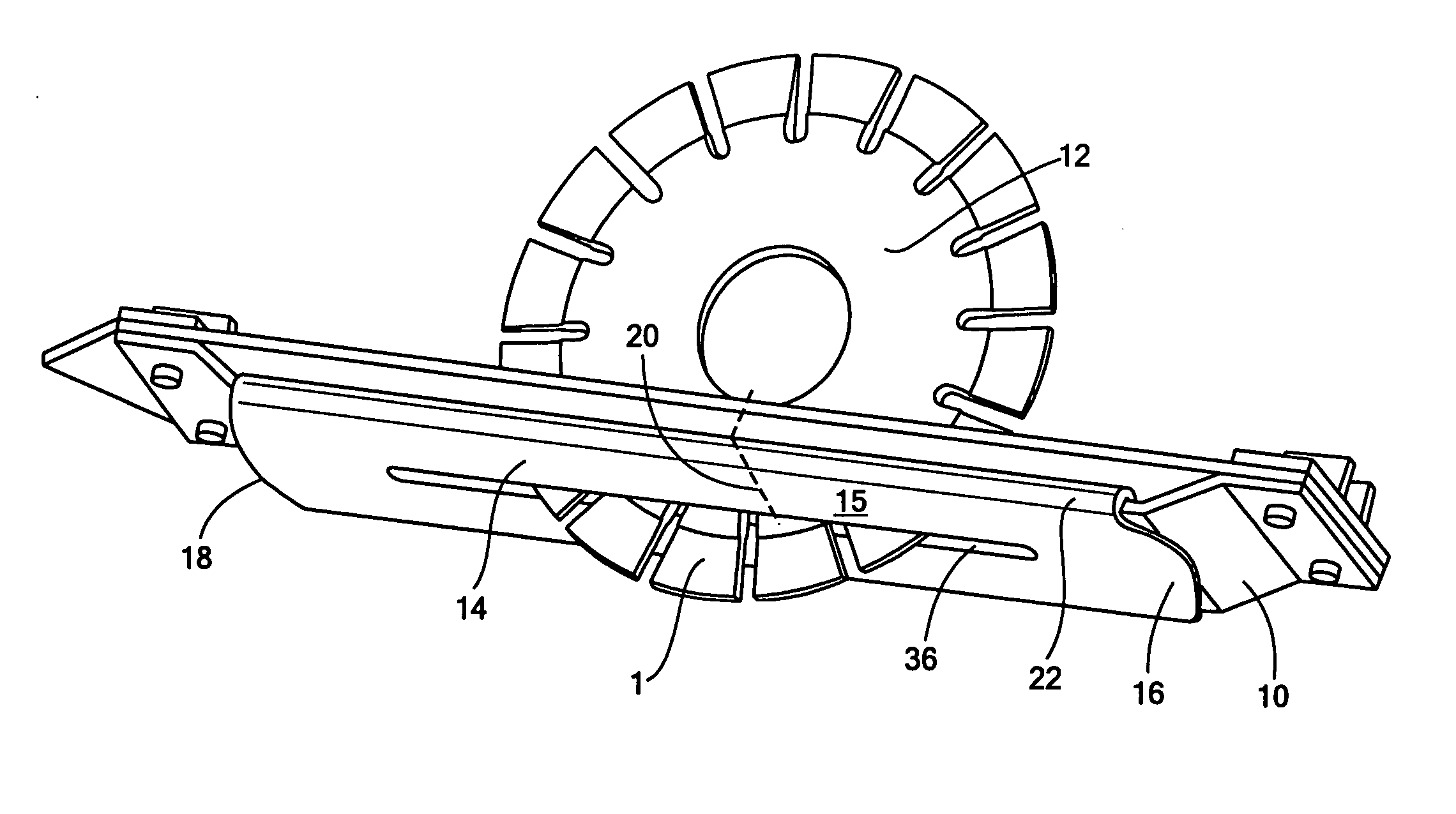
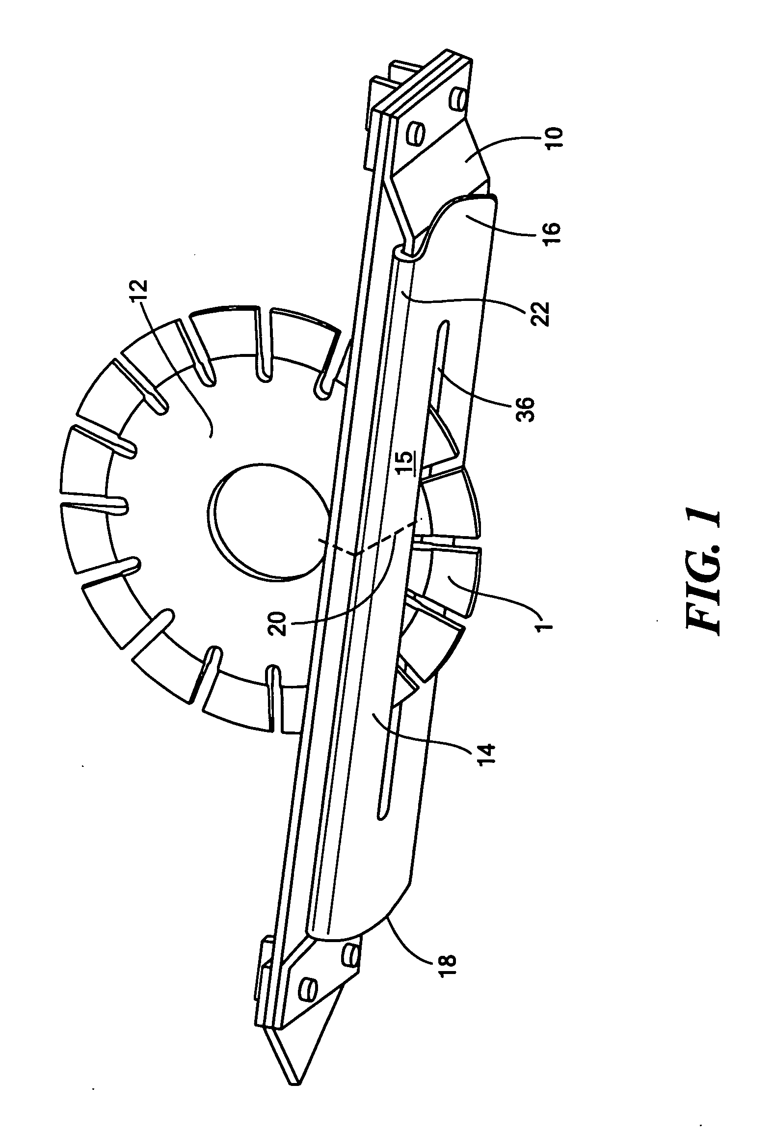
[0026]FIG. 1 shows skid plate 10 and blade 12 of a conventional concrete cutting saw. Planar skid plate shield 14, in accordance with this invention, features flat straight body 15 with leading edge 16 and trailing edge 18 although skid plate shield 14 can be installed in either orientation since shield 14 is typically sy...


PUM

PropertyMeasurementUnit
Massaaaaaaaaaa
Massaaaaaaaaaa
Fractionaaaaaaaaaa

Abstract

A saw skid plate shield including a shield plate body defining a leading edge and a trailing edge and a mechanism such as edge rails for attaching the shield plate body to the skid plate. Both the leading and trailing edges of the skid plate body are beveled and / or rounded to divert debris.

Description

RELATED APPLICATIONS [0001] The subject application is a continuation-in-part application of and claims priority from U.S. patent application Ser. No. 10 / 826,717 filed Apr. 16, 2004 which claims priority to provisional application No. 60 / 464,618 filed Apr. 22, 2003.FIELD OF THE INVENTION [0002] This subject invention relates to a saw skid plate shield useful in concrete cutting saws and other saws. BACKGROUND OF THE INVENTION [0003] The skid plate of a concrete or other saw performs three primary functions: it supports the saw as the skid plate skids across the surface to be cut, it acts as a blade guide, and it helps ensure a quality cut by the blade. When the skid plate wears, the quality of the cut made by the saw blade degrades. [0004] Thus, U.S. Pat. No. 6,736,126, incorporated herein by this reference, proposes a glide plate assembly with a specially designed plate and a plastic overlay for the plate. The skid plate of the saw is removed and the new glide plate / overlay combina...

Claims


Application Information

Patent Timeline
IPC IPC(8): B28D1/04
CPCB28D1/045B23D47/02
Inventor BURKE, MICHAEL
Owner BURKE MICHAEL
Features
  • Generate Ideas
  • Intellectual Property
  • Life Sciences
  • Materials
  • Tech Scout
  • Unparalleled Data Quality
  • Higher Quality Content
  • 60% Fewer Hallucinations
Learn More