System for positioning a workpiece

a workpiece and positioning technology, applied in the direction of process and machine control, program control, instruments, etc., can solve the problems of inability to properly rotate the workpiece, the accuracy of the log turning method is not accurate, and the lumber recovery rate is significan

Active Publication Date: 2006-03-09
USNRKOCKUMS CANCAR
View PDF20 Cites 14 Cited by
  • Summary
  • Abstract
  • Description
  • Claims
  • Application Information

AI Technical Summary

Benefits of technology

[0015] The marking device may be a spray paint marking device for placing a spray paint line on an end of the workpiece. A first camera identifies the orientation of the mark. This may be prior to the workpiece exiting the optimizer. The optimizer determines the optimized position of the workpiece. A workpiece turning mechanism such as one including a pair of turning rolls, one turning roll on each side of a conveyor, rotates the workpiece to its optimized position. The turning rolls may be spiked to grasp the workpiece without slipping. The turning rolls may also displace horizontally to engage the workpiece. They may also rotate about a vertical axis to assist in transporting the workpiece along the conveyor. The pair of turning rolls displace vertically relative to one another, upwards and downwards, causing the...

Problems solved by technology

Other conventional log turners known as knuckle turners provide a less accurate method of turning logs.
During the turning process, surface irregularities such as protruding knots or indentations on the surface of the workpiece may affect proper contact of the spiked rolls with the workpiece, thereby inhibiting proper rotation of the workpiece to position it in the optimized position.
This turning inaccuracy results in a significant reduction in lumber recovery.
Furthermore, even if the optimized position is achieved, movement of the transport conveyor on which the workpiece travels may not maintai...

Method used


Image

  • System for positioning a workpiece
  • System for positioning a workpiece
  • System for positioning a workpiece

Examples


Embodiment Construction

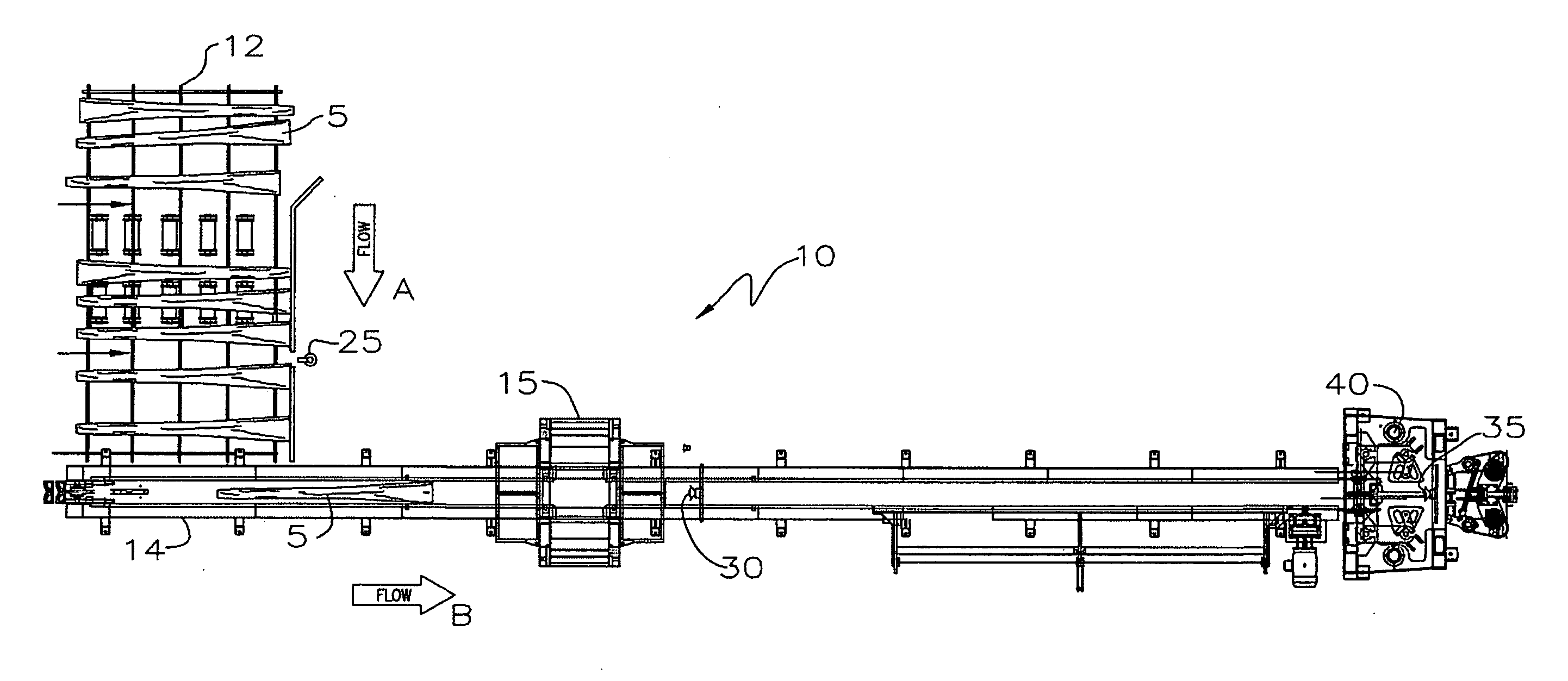
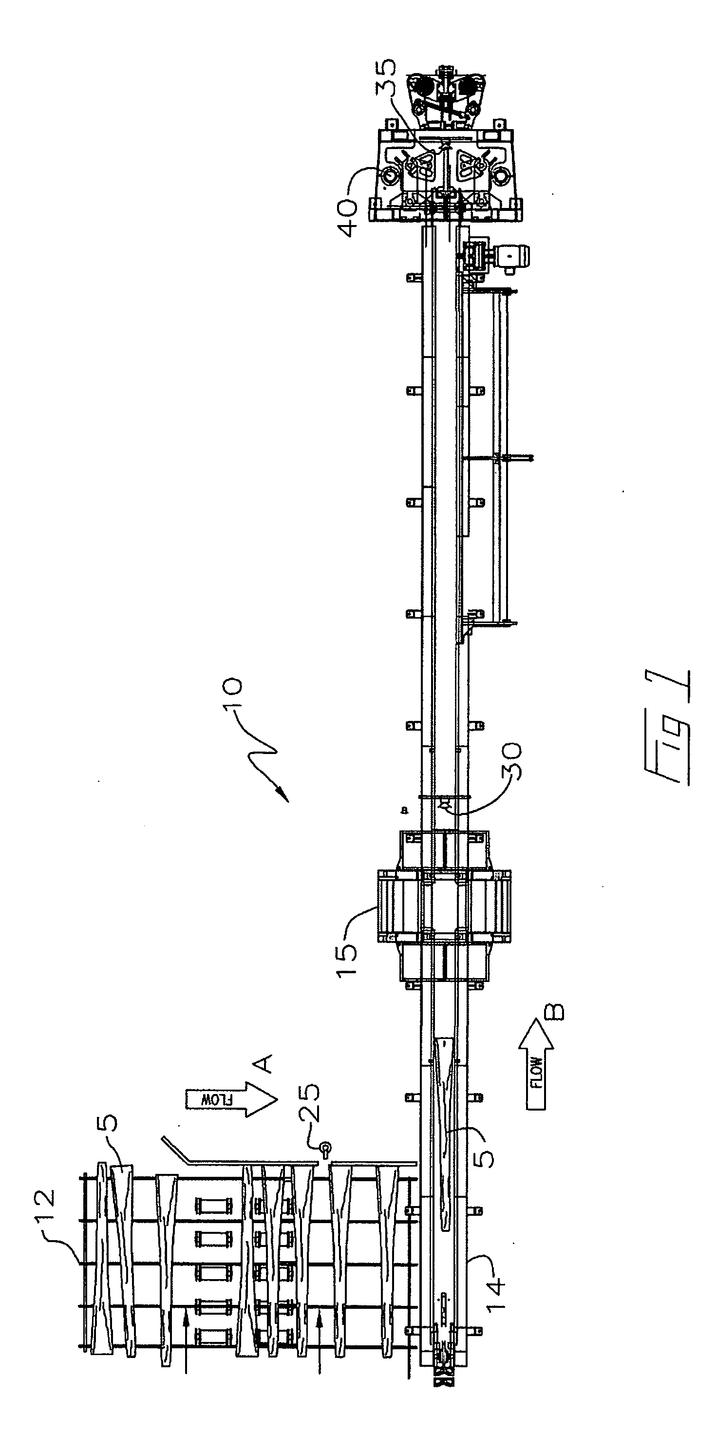
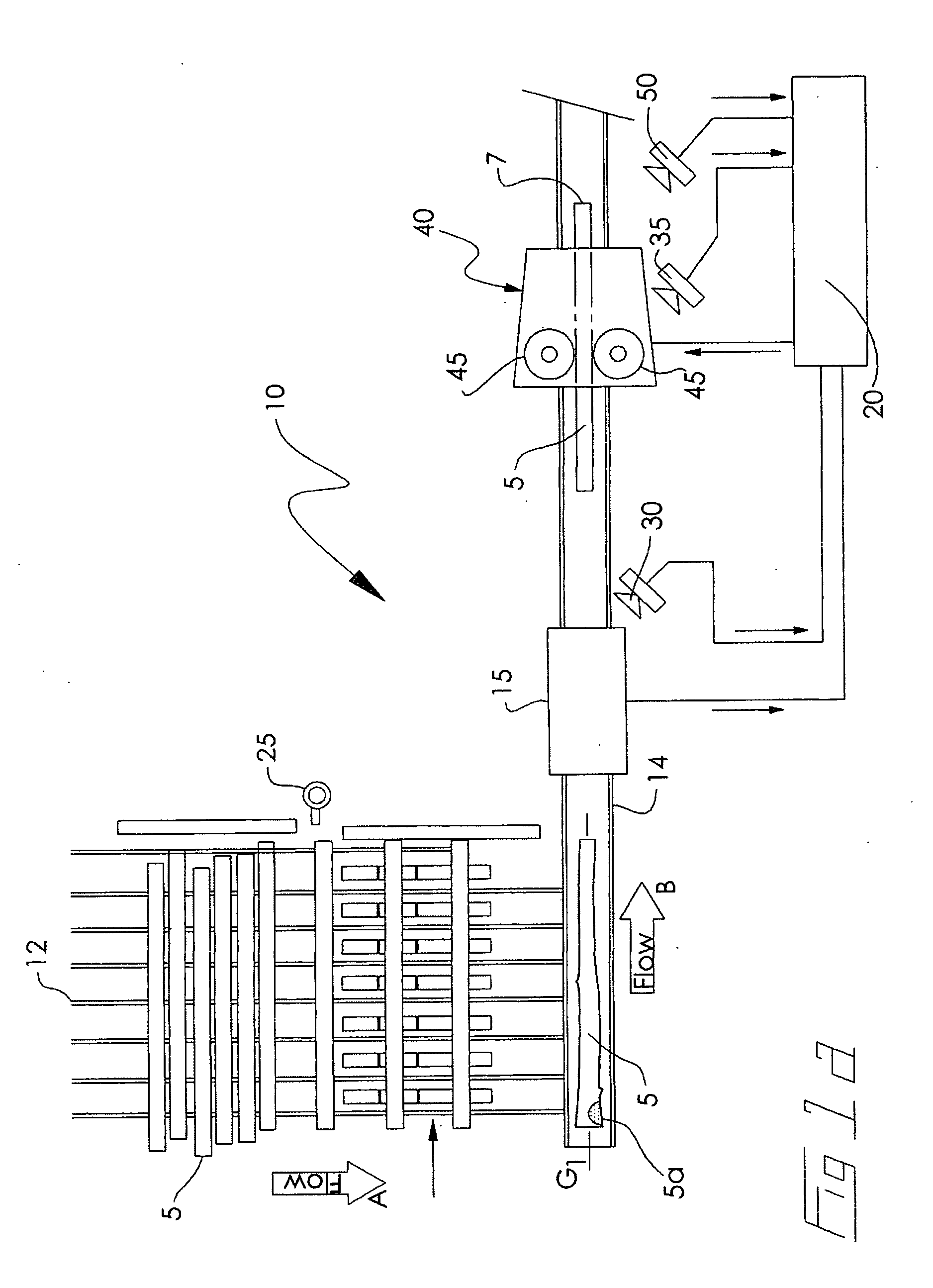
[0023] With reference to the Figures wherein similar characters of reference denote corresponding parts in each view, a system 10 according to the present invention includes a scanner / optimizer 15, a processor 20, a marking device 25, a first and a second mark orientation identifying means 30 and 35, and a turning mechanism 40.

[0024] As seen in FIGS. 1 and 1a, a plurality of logs, referred to herein alternatively as workpieces 5, located on an infeed 12 are transported by suitable means, such as a chainway or other conveyor, in downstream direction of flow A on a feedpath towards a conveyor 14. Marking device 25 mounted along infeed 12 makes or places a mark 28 on each workpiece 5. Alternatively, marking device 25 may be positionable along conveyor 14 so that marking device 25 places mark 28 on workpiece 5 prior to workpiece 5 passing through scanner / optimizer 15. In one embodiment, not intended to be limiting, marking device 25 is a spray paint marking device for placing a visuall...


PUM


Abstract

A system for positioning a workpiece in an optimized position. In one embodiment a marking device places a mark on the workpiece prior to the workpiece passing through a scanner cooperating with an optimizer. The optimizer determines the optimized position of the workpiece. The orientation of the workpiece is identified by a first camera. The mark may be used as a point of reference such that the workpiece may be positioned in the optimized position by rotating the workpiece relative to the orientation of the mark. A turning mechanism rotates the workpiece to position it in the optimized position. A further camera identifies the orientation of the mark while the workpiece is being rotated. A processor compares in real time the orientation of the workpiece with the optimized position to determine if the workpiece is in the optimized position.

Description

CROSS REFERENCE TO RELATED APPLICATION [0001] This application claims priority from U.S. Provisional Patent Application No. 60 / 608,101 filed Sep. 9, 2004 entitled System for Positioning a Workpiece.FIELD OF THE INVENTION [0002] This invention relates to the field of devices for positioning a workpiece in a sawmill, and more particularly, it relates to a system for positioning a workpiece into an optimized position to produce the highest value or yield of lumber. BACKGROUND OF THE INVENTION [0003] Conventional log turners known as “flying log turners”, typically comprise a pair of four to five foot long vertically oriented spiked rolls which are located on each side of a transporting conveyor. The log turner rotates a workpiece, such as a log or a cant, as the workpiece travels towards the infeed of a primary breakdown machine, such as a gang saw. The spiked rolls of the log turner are movable laterally towards and away from the centreline of a workpiece, longitudinally along the len...

Claims


Application Information

Patent Timeline
IPC IPC(8): B23Q15/00B23Q16/00
CPCB23Q7/001B23Q15/22B23Q17/24G05B2219/37555B27B31/06G05B2219/37097B27B31/04
Inventor BOYD, MURRAYWEBSTER, SANDYDAVYDUKE, ROLANDPOBUDA, RONALD H.FLATMAN, CARLMITCHELL, RORY M.
Owner USNRKOCKUMS CANCAR
Why Eureka
Try Eureka