
Electrical connection system

a technology of electrical connection and connection system, which is applied in the direction of electrical apparatus, casings/cabinets/drawers, casings/cabinets/drawers details, etc., can solve the problems of improper electrical grounding conditions, box interior paint accumulation, and poor electrical grounding effect, so as to facilitate engaging the connection

Inactive Publication Date: 2006-03-09
RICK ELECTRICAL CONTRACTORS
View PDF10 Cites 23 Cited by
  • Summary
  • Abstract
  • Description
  • Claims
  • Application Information

AI Technical Summary

Benefits of technology

"The present invention provides a temporary cover for an electrical box that can be easily connected and disconnected without tools. The cover is color-coded to designate the location of the electrical box and includes tabs for easy connection. The cover can also have conduit identifier supports to designate the destination of the electrical conduit. The invention provides a convenient and flexible solution for designing electrical connections."

Problems solved by technology

As many painting contractors use a spray paint method rather than a brush and roller method to apply interior paint, the boxes may likely accumulate paint residue, particularly because it is the inventor's experience that many painting contractors fail to properly cover electrical boxes prior to painting.
This can leave a substantial paint build-up or over-spray in the interior of the boxes.
Drywall mud and paint overspray deposits, for example, on electrical boxes can result in improper electrical grounding conditions, in direct violation of the current 2005 National Electrical Code (2005 NEC) and the 2000 International Building Code, for example.
Improper grounding conditions caused by deposits of unwanted foreign materials may also hamper the ability of the electrician to identify how the electrical boxes are to be wired after (e.g.) the inside gypsum board or wall material is installed, since arrows or other indications for wiring on or in the vicinity of the boxes may now be partially or entirely covered by, e.g., mud or paint spray residue or deposits.
Accordingly, there is a need for a temporary, inexpensive electrical box cover to shield an electrical box during construction phases which, absent shielding, might receive substantial unwanted foreign material deposits potentially resulting in improper electrical grounding conditions and, thus, potentially serious electrical safety issues due to improper grounding of receptacles, switches, wiring, conduit systems, fixtures and / or boxes, etc.

Method used


Image

  • Electrical connection system
  • Electrical connection system
  • Electrical connection system

Examples


Embodiment Construction

[0033] Set forth below is a description of what are believed to be the preferred embodiments and / or best examples of the invention claimed. Future and present alternatives and modifications to this preferred embodiment are contemplated. Any alternatives or modifications which make insubstantial changes in function, in purpose, in structure, or in result are intended to be covered by the claims of this patent.

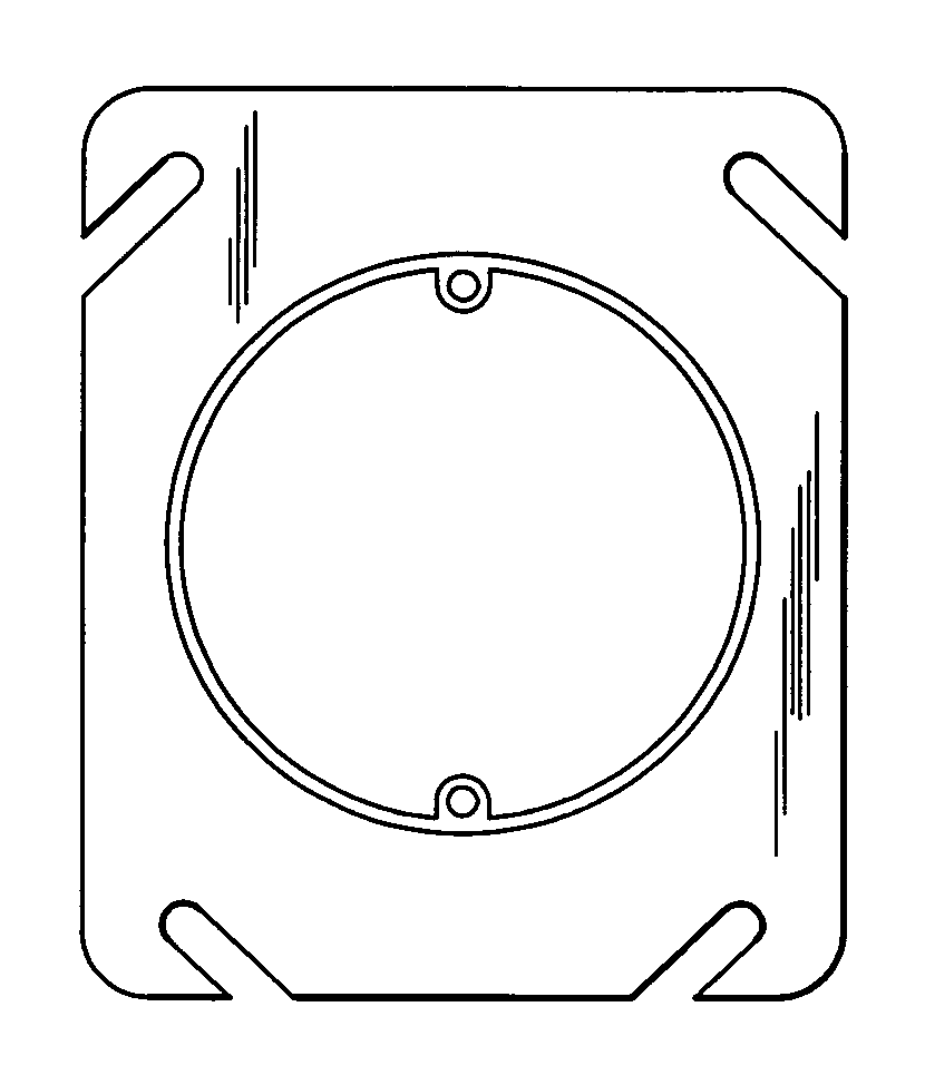
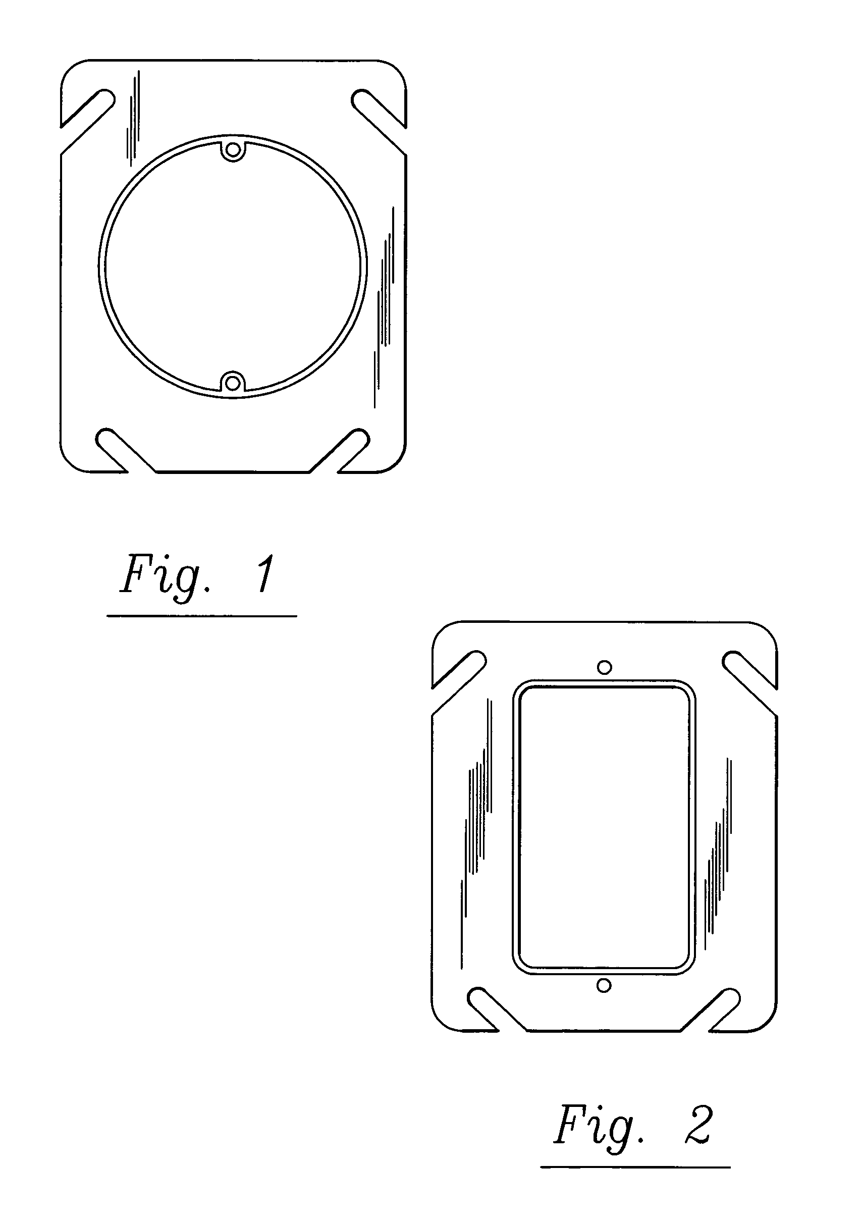
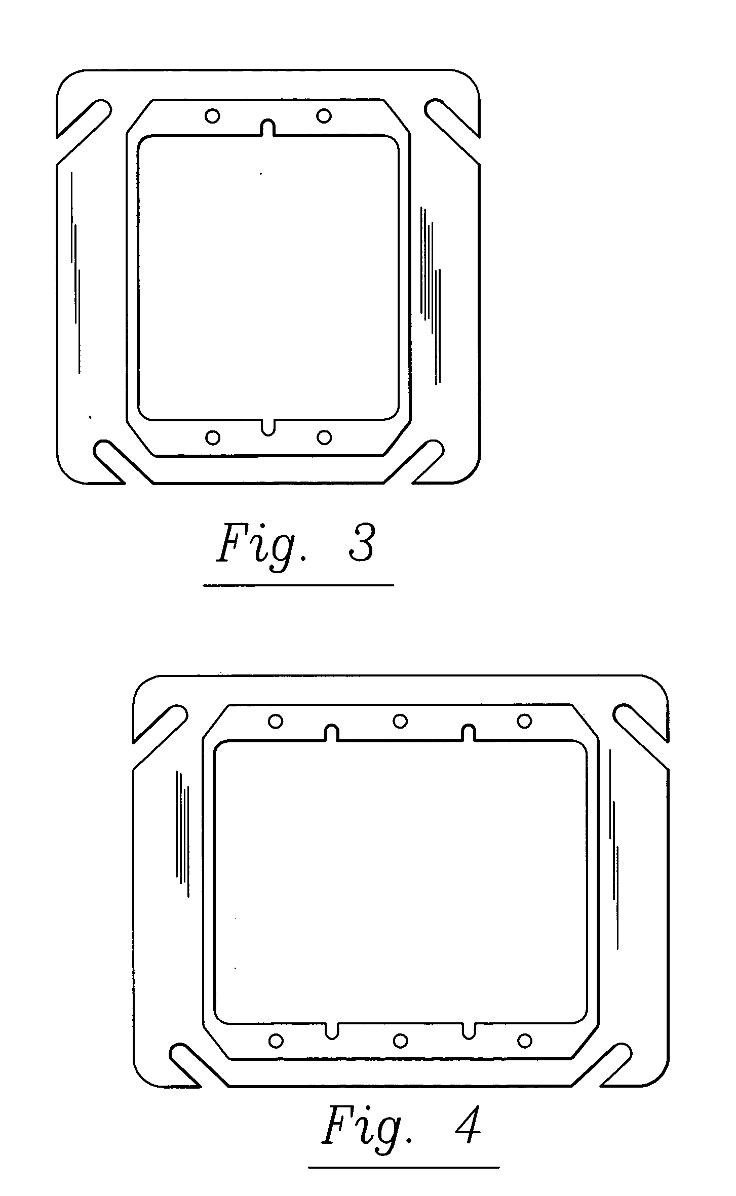
[0034] In accordance with one embodiment of this invention, and referring now to FIGS. 12-17, temporary electrical covers according to one preferred embodiment of the present invention, and designated generally with the reference numeral 10, are shown. Referring to FIG. 12, color-coded covers 10 are preferably employed, using a color-coding scheme familiar to electricians as further explained below, with “G” referring to a temporary cover colored green, “Y” referring to yellow and “R” to red. Of course, other colors may be used, as well.

[0035] Preferably, temporary box cover 1...


PUM


Abstract

An electrical connection system which may include color-coded, temporary covers for electrical boxes, and may also include color-coded conduit identifiers such as removable caps or collars. The color-coded covers may provide origination information for the electrical box so covered, while the color-coded conduit identifiers may provide destination information for electrical conduit so identified.

Description

BACKGROUND OF THE INVENTION [0001] The present invention relates to the construction industry and, more specifically, to an inexpensive, disposable, color-coded cover for temporarily covering electrical receptacles, switch boxes and the like during wall finishing such as plastering, drywalling, gypsum boarding, masonry, cementing, wooden sheathing, wooden planking, paneling, ceramic tiling, etc. to avoid their contamination during those building phases, and also to facilitate subsequent work performed by electrical tradesman. Inexpensive, disposable and color-coded conduit identifiers may also be used to facilitate electrical contractor operations. [0002] As technology has advanced, the need for electrical power and highly desirable low voltage communications cabling such as Structured Cabling applications (i.e. voice, data, video, home theater, security, broadband, etc.) to be provided throughout a building has also increased. Currently, a typical 2000 sq. ft. single family home in...

Claims


Application Information

Patent Timeline
Patent Type & Authority Applications(United States)
IPC IPC(8): H02G3/14
CPCH02G3/126
Inventor RICK, KEVIN W.
Owner RICK ELECTRICAL CONTRACTORS
Learn More