Method and structure for waterproofing a terminal splice

a technology of a terminal splice and a structure, which is applied in the direction of connection end caps, cable terminations, coupling devices, etc., can solve the problems of reducing space efficiency, and increasing the cost of waterproofing agents, so as to reduce the size of the external part, reduce the use of waterproofing agents, and reduce the size of the cap

Active Publication Date: 2006-03-09
SUMITOMO WIRING SYST LTD
View PDF12 Cites 31 Cited by
  • Summary
  • Abstract
  • Description
  • Claims
  • Application Information

AI Technical Summary

Benefits of technology

[0008] The present invention is provided to address at least the above noted shortcomings, to reduce the diameter of a cap necessary to cover a terminal splice and to improve workability and waterproof performance.
[0009] An aspect of the present invention provides a method of waterproofing a terminal splice including providing a heat shrinkable tube, the heat shrinkable tube having a first opening and a second opening; inserting a stopper in the first opening of the heat shrinkable tube; heat-shrinking the heat shrinkable tube having the stopper inserted therein, forming a cap having an end closure; injecting a fluid waterproofing agent into the cap through the second opening; inserting a terminal splice through the second opening of the cap and immersing the terminal splice in the waterproofing agent; and heating the cap at a predetermined temperature to heat-shrink the heat shrinkable tube and to accelerate hardening of the waterproofing agent.

Problems solved by technology

Since cap 1 used is large even if terminal splice Y is small, the cap occupies a space when terminal splice Y is placed in an external part, reducing space efficiency.
Especially, when terminal splice Y is placed into a corrugated tube, a large-diameter corrugated tube is required, resulting in cost increase.
In addition, the larger the internal diameter of cap 1 becomes, the more waterproofing agent 2 is required for the injection, which increases the cost of waterproofing agent 2.
Using butyl rubber 6 of low fluidity as filler, however, reduces workability when injecting butyl rubber 6 inside heat shrinkable tube 4.

Method used


Image

  • Method and structure for waterproofing a terminal splice
  • Method and structure for waterproofing a terminal splice
  • Method and structure for waterproofing a terminal splice

Examples


Embodiment Construction

[0027] The particulars shown herein are by way of example and for purposes of illustrative discussion of the embodiments of the present invention only and are presented in the cause of providing what is believed to be the most useful and readily understood description of the principles and conceptual aspects of the present invention. In this regard, no attempt is made to show structural details of the present invention in more detail than is necessary for the fundamental understanding of the present invention, the description is taken with the drawings making apparent to those skilled in the art how the forms of the present invention may be embodied in practice.

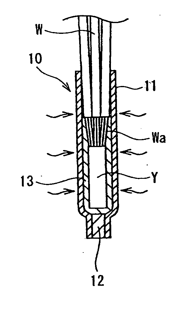
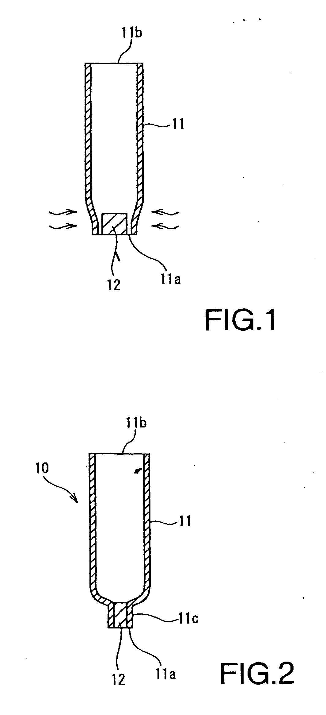
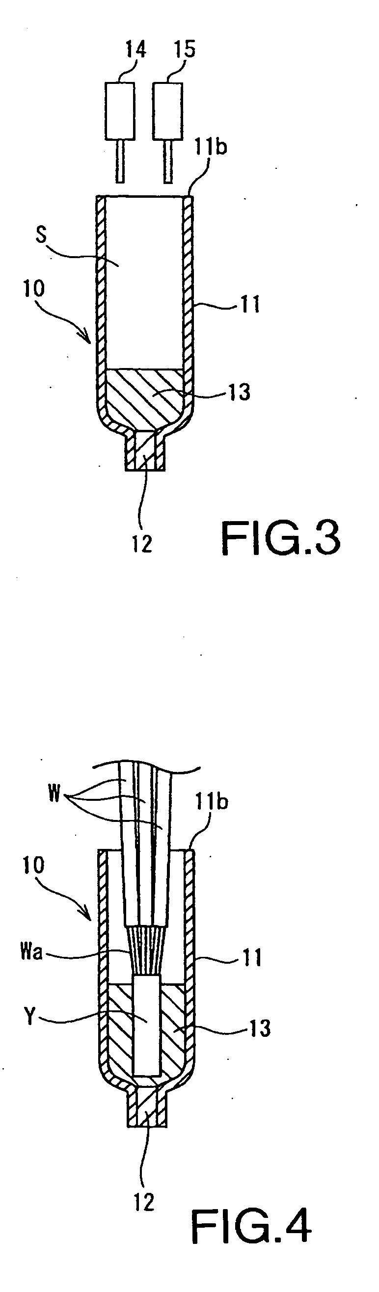
[0028] The following describes an embodiment of the present invention with reference to the drawings. FIGS. 1, 2, 3, 4 and 5 illustrate procedures of the method that waterproof a terminal splice according to the embodiment of the present invention. As shown in FIG. 1, heat shrinkable tube 11 has a first, slightly heat-shrunk...


PUM


Abstract

To decrease cap diameter covering a terminal splice and improve workability and waterproof performance, a stopper is inserted in one opening of a heat shrinkable tube. The heat shrinkable tube is heat-shrunk in this state, then a cap having end an closure is formed. A fluid thermosetting waterproofing agent is injected into the cap from a second opening. A thermal splice, which is formed from welded strands stripped from a plurality of wire terminals, is inserted and immersed in the thermosetting waterproofing agent. Then, the entire cap is heated and heat-shrunk at a predetermined temperature and the thermosetting waterproofing agent is heat-hardened.

Description

CROSS-REFERENCE TO RELATED APPLICATIONS [0001] The present disclosure relates to subject matter contained in priority Japanese Application No. 2004-263025, filed on Sep. 9, 2004, which is herein expressively incorporated by reference in its entirety. BACKGROUND OF THE INVENTION [0002] 1. Field of the Invention [0003] The present invention relates to a method and a structure for waterproofing a terminal splice, and in particular for waterproofing the terminal splice at a location where strands stripped from a plurality of wire terminals are connected. [0004] 2. Description of Related Art [0005] A conventional method to electrically connect wires of a wire harness routed in an automobile is, as shown in FIG. 6, to weld and join strands Wa stripped from a plurality of wire W terminals to form a terminal splice Y. Waterproofing is required when terminal splice Y is placed in an area exposed to water as the wire harness is installed in a vehicle. FIG. 6 illustrates a conventional waterpr...

Claims


Application Information

Patent Timeline
Patent Type & Authority Applications(United States)
IPC IPC(8): H02G3/02
CPCH01R4/029H01R4/22H01R4/72H01R13/52H02G15/1806H01R13/5221H01R43/005H02G15/043H01R13/5216
Inventor OOTSUKI, HIROYUKI
Owner SUMITOMO WIRING SYST LTD
Why Eureka
Try Eureka