
Control apparatus for hybrid vehicle

Inactive Publication Date: 2006-03-09
HONDA MOTOR CO LTD
View PDF8 Cites 58 Cited by
  • Summary
  • Abstract
  • Description
  • Claims
  • Application Information

AI Technical Summary

Benefits of technology

[0013] According to the first aspect of the present invention, when it is determined by the drive mode determination device that a mode transition from a current drive mode to another drive mode should take place, a transition rate modification device modifies a transition rate for transitioning from the current drive mode to the another drive mode according to the drive mode to be transitioned. Therefore, it is possible to modify the required electric power according to the drive mode to be transitioned. In addition, it is possible to drive the vehicle in the current drive mode while saving electric power suitable to each of the drive modes. Thus, the engine stop EV drive mode allowable region and the idle cylinder deactivation EV drive mode allowable region can be enlarged, thereby improving the fuel consumption.
[0043] According to the eleventh aspect of the present invention, it is possible to reduce the friction from the engine, thereby contributing to an improvement in the fuel consumption.

Problems solved by technology

In a conventional vehicle without an electric motor, deceleration energy generated during deceleration of the vehicle is wasted in a form of heat by means of a friction brake.
Therefore, when the vehicle is driven only by the motor, electric power sufficient to transition to an engine drive mode must be saved in the battery all the time, which restricts the motor only drive allowable region.
As a result, even when the motor is able to output the requested driving force, a transition to the engine drive mode may occur, which hinders achieving an improvement in the fuel consumption.

Method used


Image

  • Control apparatus for hybrid vehicle
  • Control apparatus for hybrid vehicle
  • Control apparatus for hybrid vehicle

Examples


Embodiment Construction

[0062] Hereinafter, a control apparatus for a hybrid vehicle according to embodiments of the present invention will be described with reference to the drawings.

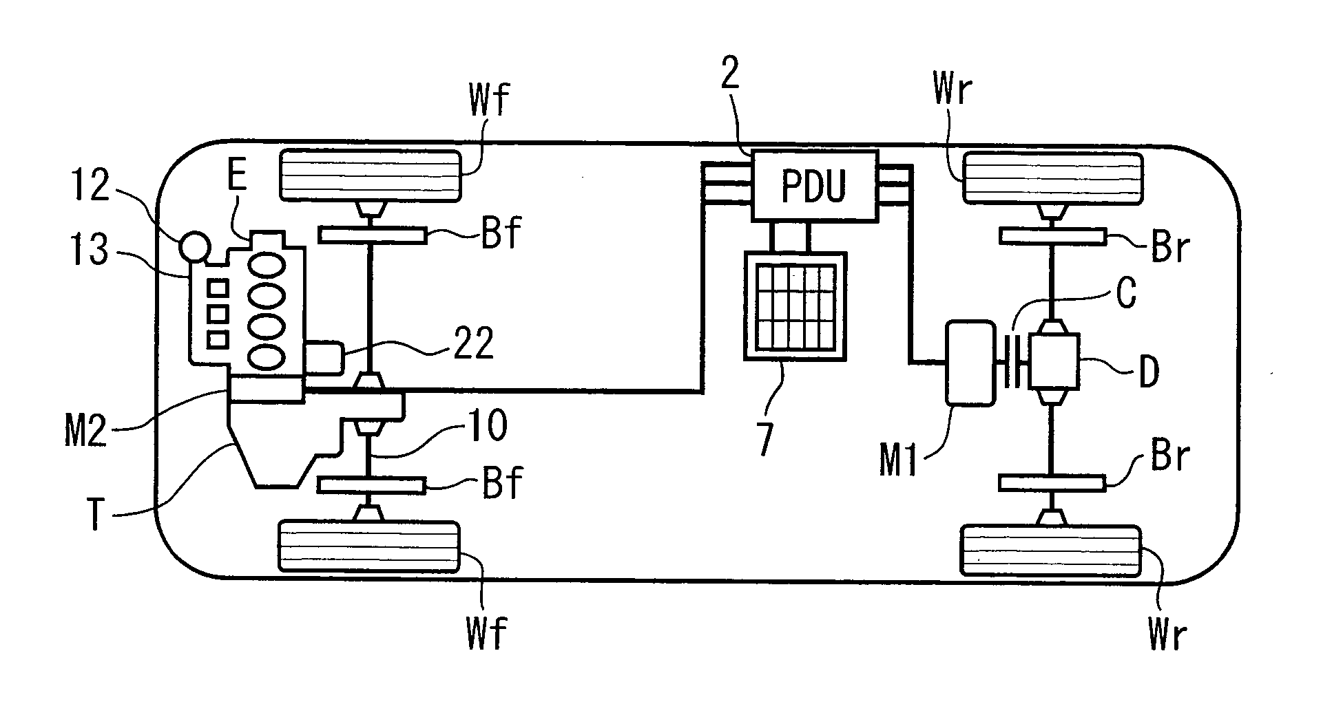
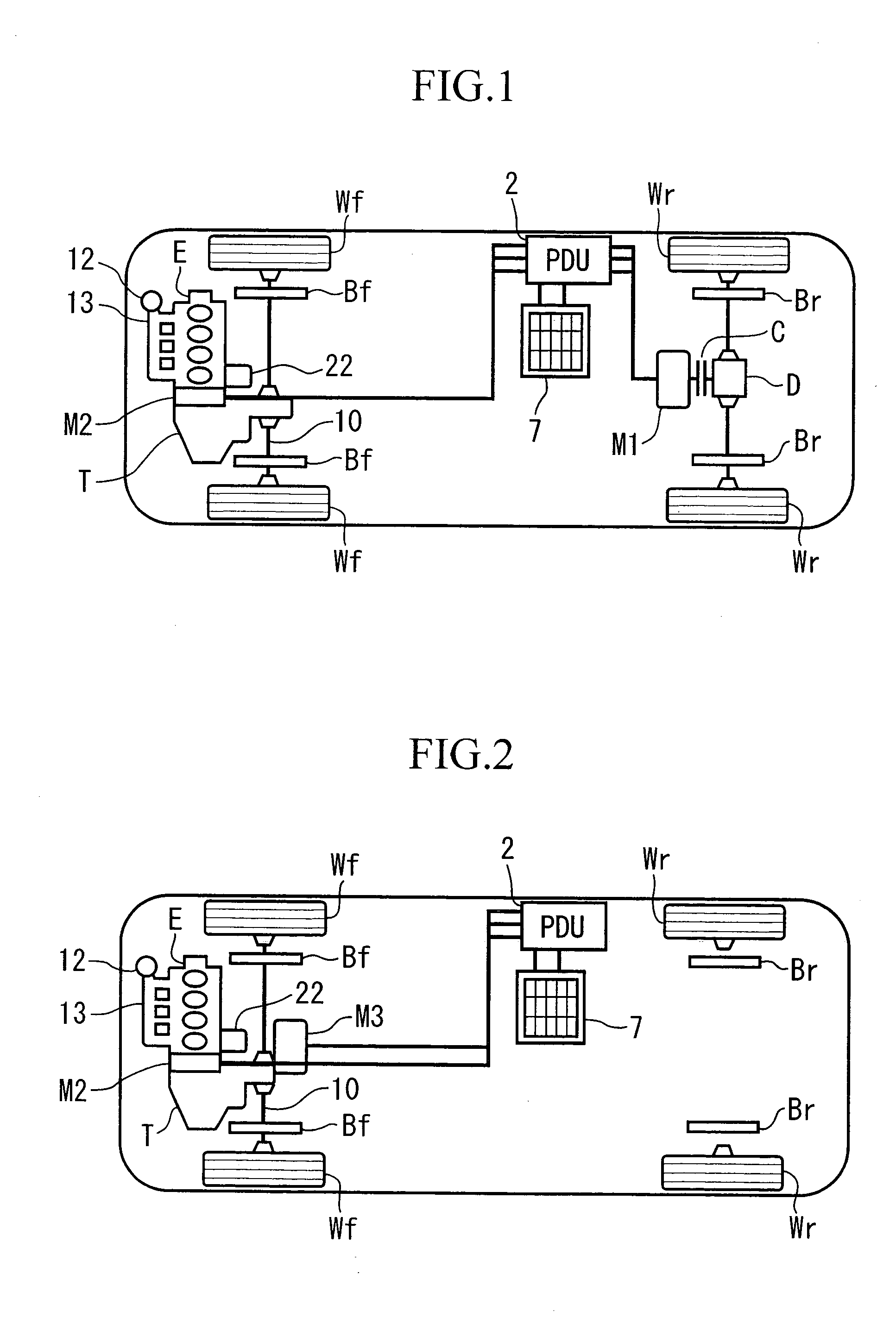
[0063]FIG. 1 is a schematic diagram of a drive hybrid vehicle to which the present invention is applied.

[0064] The hybrid vehicle shown in FIG. 1 is a four-wheel drive vehicle that includes an engine E and a motor M2 in the front side of the vehicle, and a motor M1 that is connected to the an input of the differential gear D in the rear side. In this embodiment, the motor M1 in the rear side primarily functions as a traction motor, and the motor M2 in the front side primarily functions as a generator. Accordingly, these motors are refereed to as the traction motor M1 and the generator motor M2 where appropriate.

[0065] In this example, the motor M2 is positioned between the engine E and a transmission T having a clutch for the transmission. Furthermore, the clutch for the transmission (not shown) is provided that mechanical...


PUM


Abstract

A control apparatus for a hybrid vehicle includes: a drive mode determination device that determines one drive mode from a plurality of drive modes based on a status of the vehicle, wherein the drive modes include: an engine stop motor drive mode in which the vehicle is driven by a driving force from a motor while stopping an engine; an idle cylinder deactivation motor drive mode in which the vehicle is driven by the driving force from the motor by operating a power generator as an electric motor by running the engine while maintaining the engine deactivated; and an engine drive mode in which the vehicle is driven by a driving force from the engine; and a transition rate modification device that, when it is determined by the drive mode determination device that a mode transition from a current drive mode to another drive mode should take place, modifies a transition rate for transitioning from the current drive mode to the another drive mode according to the drive mode to be transitioned.

Description

BACKGROUND OF THE INVENTION [0001] 1. Field of the Invention [0002] The present invention relates to a control apparatus for a hybrid vehicle including an engine and a motor as driving sources for driving the vehicle, a power generator driven by the engine, and an electric storage device for storing regeneration energy from the power generator and the motor. [0003] Priority is claimed on Japanese Patent Application No. 2004-256859, filed Sep. 3, 2004, the content of which is incorporated herein by reference. [0004] 2. Description of Related Art [0005] A hybrid vehicle has been known in which an engine that is connected to a geared or continuous variable speed automatic transmission and drives main driving wheels (i.e., the front wheels or the rear wheels) and a motor that directly drives the axle shaft via reduction gears, in which the motor is connected to a battery and is placed on the crank shaft for restarting the engine that has been stopped. In such a hybrid vehicle, by proper...

Claims


Application Information

Patent Timeline
IPC IPC(8): B60K6/00B60K6/38B60L50/16B60K6/44B60K6/52B60K17/04B60K17/356B60W10/06B60W10/08B60W20/00F02D13/02F02D29/06
CPCB60K6/44B60K6/52B60L2240/445B60L2240/485B60W10/06B60W10/08Y02T10/6286B60W2510/0676B60W2510/107B60W2540/106B60W2550/142Y02T10/623Y02T10/6265B60W20/00B60W2552/15Y02T10/62B60W2510/244B60W50/08
Inventor YAMAMOTO, AKIHIROYAMAMOTO, KAZUHISA
Owner HONDA MOTOR CO LTD
Learn More