Lock-up clutch control device for vehicle

Active Publication Date: 2017-05-04
NISSAN MOTOR CO LTD
View PDF3 Cites 9 Cited by
  • Summary
  • Abstract
  • Description
  • Claims
  • Application Information

AI Technical Summary

Benefits of technology

The present invention aims to improve fuel efficiency in a lock-up clutch re-engagement control system by reducing engagement shock. The invention controls the engine torque and synchronizes the engine speed with the turbine speed to quickly engage the lock-up clutch during an accelerator foot release. This reduces the engagement shock and improves fuel efficiency while driving in a slip engagement mode.

Problems solved by technology

However, when a fuel cut-off state occurs during slip engagement operation in response to release of a foot from an accelerator, the lock-up clutch will be rapidly engaged due to overcapacity of the lock-up clutch to cause engagement shock to occur.
However, due to the lock-up release, there is a problem that the fuel consumption is deteriorated.

Method used


Image

  • Lock-up clutch control device for vehicle
  • Lock-up clutch control device for vehicle
  • Lock-up clutch control device for vehicle

Examples


Embodiment Construction

[0016]Below, a description will be given of the best mode for implementing the lock-up clutch control device for a vehicle according to the present invention with reference to a first embodiment shown in the drawings.

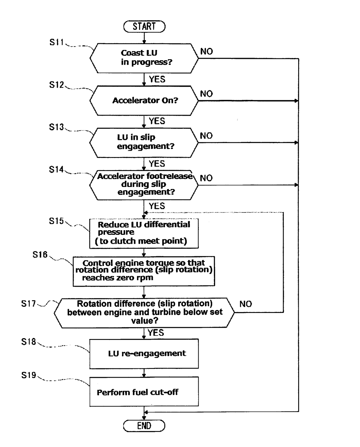
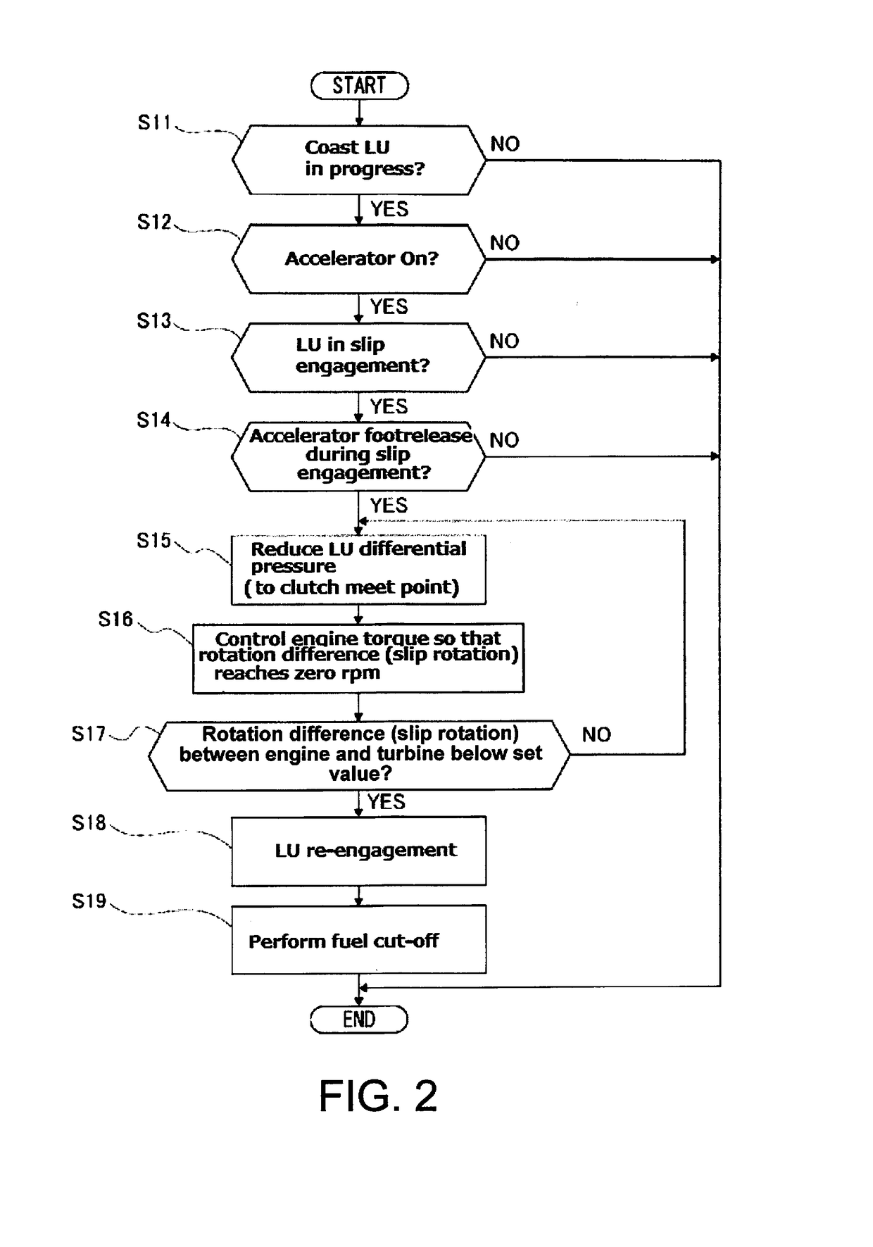
[0017]First, the configuration will be described. The configuration of the lock-up clutch control device for a vehicle in the first embodiment is now separately discussed in the “overall system configuration”, “coast lock-up control process configuration from slip engaging state”, “coast lock-up control process configuration from in a lock-up engaging state”, respectively. Overall System Configuration

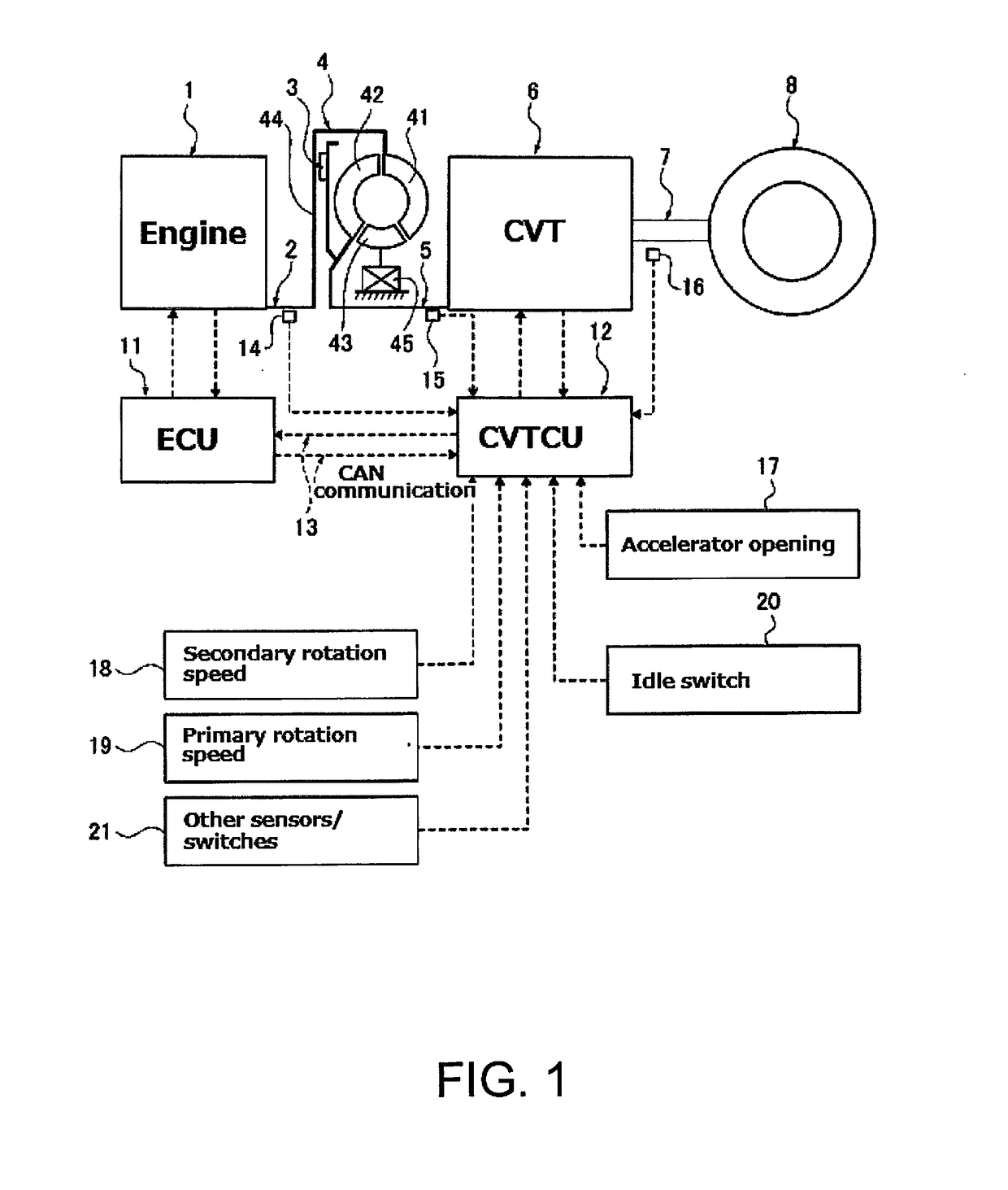
[0018]FIG. 1 shows an engine vehicle in which the lock-up clutch control device of the first embodiment is applied. Below, with reference to FIG. 1, a description is made of the overall system configuration.

[0019]A vehicle drive system, as shown in FIG. 1, is provided with an engine 1, an engine output shaft 2, a lock-up clutch 3, a torque converter 4, and a transmission in...


PUM


Abstract

A lock-up clutch control device is provided for a vehicle, in which, when the accelerator pedal is released in a slip engagement mode, lock-up re-engagement with reduced engagement shock is performed, thereby improving fuel economy. A torque converter having a lock-up clutch is disposed between an engine and a continuously variable transmission. The vehicle is provided with a coast lock-up control unit configured to bring the engine in a fuel cut-off state when the accelerator pedal is released in a slip engagement mode in which a differential rotation is present in the lock-up clutch with the accelerator pedal being depressed. Upon accelerator fool release operation, the coast lock-up control unit performs an engine torque control to synchronize engine rotation speed and turbine rotational speed, re-engages the lock-up clutch in a rotation synchronization state, and, after the re-engagement, and performs fuel cut-off.

Description

CROSS-REFERENCE TO RELATED APPLICATIONS[0001]This application is a U.S. National stage application of International Application No. PCT / JP2014 / 073222, filed Sep. 3, 2014.[0002]BACKGROUND[0003]Field of the Invention[0004]The present invention relates to a lock-up clutch control device for a vehicle which performs a coast lock-up control, when an engine is in a fuel cut-off state with a foot release operation.[0005]Background Information[0006]A technique is known in which, in response to an accelerator being on from a coast condition, in order to alleviate shock, a lock-up clutch is temporarily brought in a slip engagement state (e.g., see International Patent Publication No. WO 2012 / 172840 A1).SUMMARY[0007]However, when a fuel cut-off state occurs during slip engagement operation in response to release of a foot from an accelerator, the lock-up clutch will be rapidly engaged due to overcapacity of the lock-up clutch to cause engagement shock to occur. For this reason, in response to ...

Claims


Application Information

Patent Timeline
IPC IPC(8): B60W30/18B60W10/06B60W10/02
CPCB60W30/18072B60W10/026B60W10/06B60W2510/0241B60W2710/0666B60W2710/024B60W2710/025B60W2710/0627B60W2540/10F16H61/143F16H2061/145Y02T10/60
Inventor TOHTA, YUZURU
Owner NISSAN MOTOR CO LTD
Why Eureka
Try Eureka